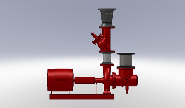
The pump discharge is the most turbulent location in a hydronic system. There are simple rules to follow when piping up a pump discharge. Today, the R. L. Deppmann Monday Morning Minutes offers thoughts to help the engineer design the pump discharge layout and for the contractor to install the centrifugal pump and trim.
Pump Discharge Pipe Size
Last week, in Hydronic Centrifugal Pumps – Closed System Suction Piping, we looked at the suction side of the pump and offered sizing tips. The discharge pipe sizing also has rules to follow.
- We introduced the Hydraulic Institute, or HI, in the last blog post. HI standards set the maximum pump discharge pipe velocity at 15 feet per second (FPS). There will be a comment to drop this lower under the check valve suggestions below.
- The discharge pipe should never be smaller than the pump discharge size.
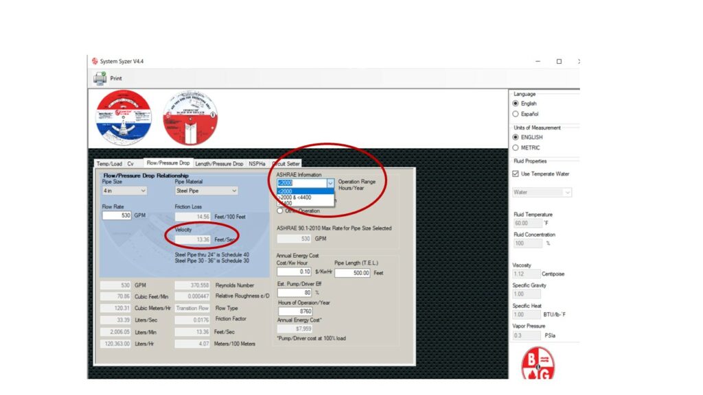
The ASHRAE 90.1 Energy Standard for Buildings offers pipe sizing limitations. That standard is also part of most State Energy Codes such as Michigan. Using the standard pipe sizing will keep the velocity below the HI limitations. Visit Hydronic Chilled & Condenser Water Pipe Sizing for more details.
We are representatives for Bell & Gossett. Using the B&G System Syzer for pipe sizing is a great way to keep within the HI limitations.
There are other equipment limitations which may suggest you keep the velocity lower than the HI maximum, so please read on.
Pump Size to Pipe Size Transition
Very often the pump discharge size is much smaller than the pipe size. This is particularly true in large 3500 RPM selections. The method of transition from the small pump discharge to the pipe size belongs in the contract documents.
The transition could be a concentric reducer or a reducing flexible connector (see 7 Tips to Save on Labor Hours in Hydronic/Steam Building Projects). Deppmann recommends keeping the reducer to a maximum of two size changes.
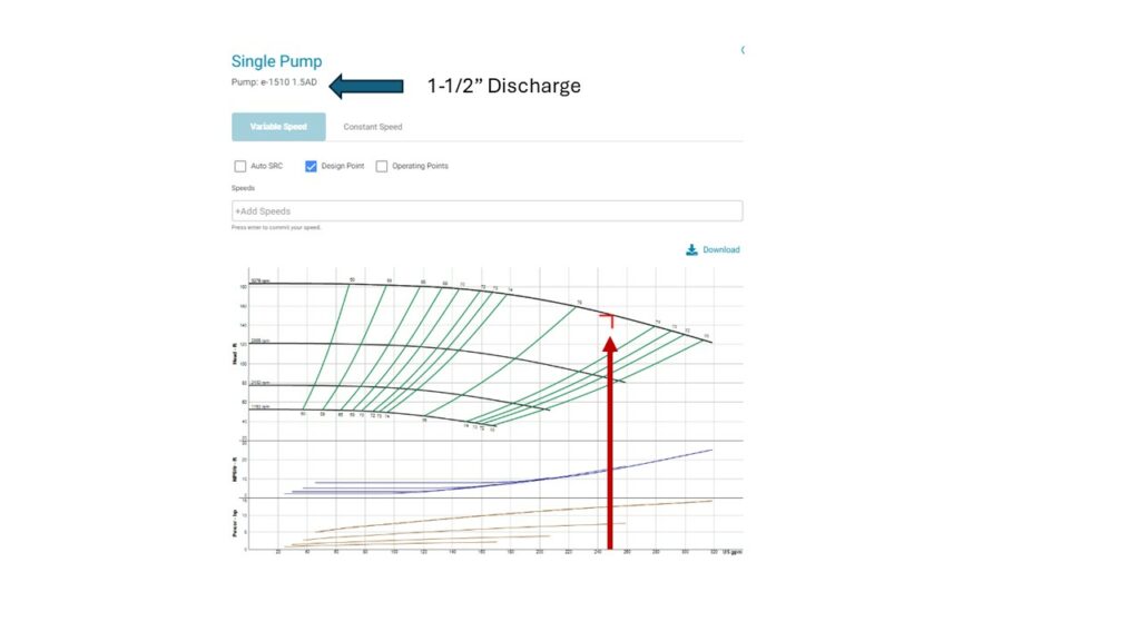
Look at the example shown here from the B&G esp-Systemwize program. The flow rate is 250 GPM. The engineer selected 4” pipe to meet the energy code.
The pipe discharge is 1-1/2” in this unusual 3500 high head selection. This is a transition of four pipe sizes. The recommendation would be for two transitions.
Maybe a solution could be a 1-1/2” to 2-1/2” reducer and a Model RMF Reducing Flexible Pump Connector from Metraflex model RMF-0425 4” by 2-1/2” reducing flanged stainless steel flex connector.
This does not happen very often, but it will come up at times.
Flexible Connectors and Sizing
The next item we often see is the flexible connector. They are normally piping size. We will take the subject of flexible connectors up in a Monday Morning Minute next month.
Check Valves and Sizing
The next item we see on the pump discharge is the check valve. There are many types and models of check valves. The differences between them will be in a later blog. There are two things to note about sizing and installation for this article:
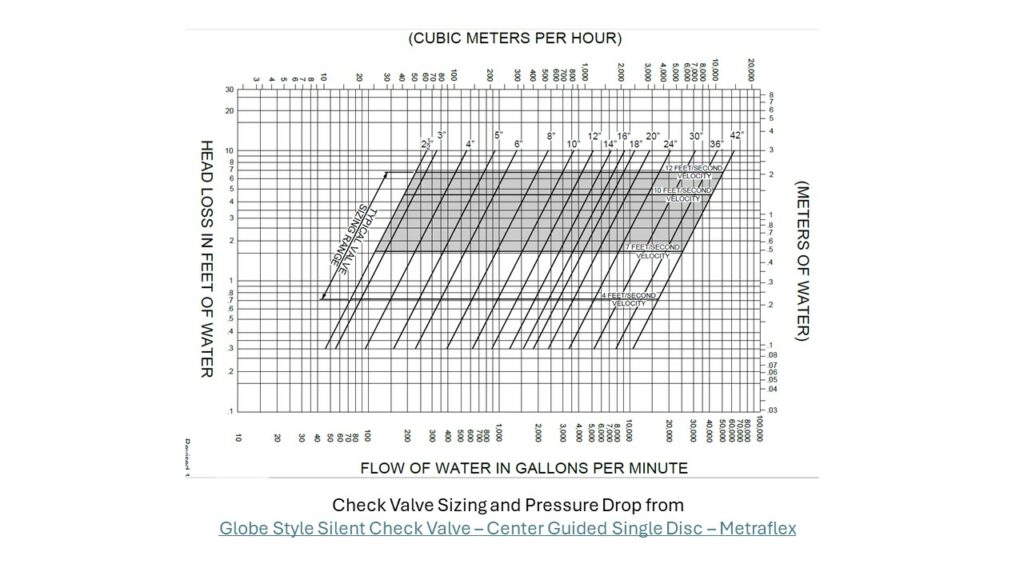
- Metraflex, and others, suggest the normal sizing range for check valves is between 4 FPS and 12 FPS. This is less than the HI maximum for the pipe size. This sets the new maximum velocity to 12 FPS.
- An installation item about check valves is one that most people do not know about. Most check valve manufacturer’s IOM requires a straight length of 5 to 10 pipe diameters into the valve. We rarely see this on installations but it does come up when the owner says, “Why is my Check Valve Chattering?”
Balance Valves and Shut Off Valves
The last two items to mention are the balance and shut off valves. The balance valve on the pump discharge serves to compensate for oversizing of the pump head in constant speed pumps. In variable speed you may use the drive to manually reduce the maximum speed. You may or may not want a balance valve on your variable speed pumps. Read more here:
- Triple Duty® valves on your variable speed hydronic pumps
- Hydronic Pump Balance using the VFD with a Triple Duty Valve
- HVAC Hydronic Pumps: B&G Triple Duty Valve for Proportional Balance
A Bell & Gossett triple duty valve can replace the check, balance, and shutoff valves. Their use frequently saves on installation costs. The triple duty valve should be sized for the flow rate and not just the pipe size. Visit Triple Duty® valves on your variable speed hydronic pumps for more about sizing the valves.
Variable Speed Hydronic Pumps | Triple Duty Valve Ports
The discharge shutoff or service valve may be the balance valve. If there is no balance valve, then a shutoff valve is required for service.
Flow Meters
A quick note about flow meters on pump discharges. Do not do it! This is the most turbulent place in the hydronic system, and you cannot get the straight diameters of pipe length needed for accuracy. Here are some thoughts:
Preso Ellipse Flow Meters for HVAC Hydronic Mains
Next week we will look at the open systems.

