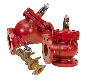
 The ASHRAE Standard 90.1-2013 and the State of Michigan 2015 Energy Code both require the trimming of impellers or reduction in the maximum speed when pumps 10 HP and above are oversized and the energy savings is 5% or 3 HP, whichever is greater. Almost all pumps are oversized. So how does the construction team determine what speed to set the drive at when the pump is oversized? The contractor can use the discharge Bell & Gossett Triple Duty Valve to accomplish this code requirement.
Proportional Balancing of Hydronic Systems
Professional balancing contractors use a process called proportional balancing to accurately set hydronic system flow rates. This process is also required by the aforementioned code. This is a preferred method over a simple read and set method. In a read and set method, the balance valves out in the system are throttled more than would be necessary if the pump was not oversized. All of the excess pump head is distributed over the system balance valves and will be an energy waste forever. In a proportional balance, the excess pump head is captured across the discharge balancing device. The hydraulically farthest balance device is wide open and has the least pressure loss it could have at design flow. Where does the excess pressure drop or pump head show up? It is across the discharge balance valve or B&G Triple Duty Valve.
Determining the Excess Pump Head after Proportional Balance
Organizations such as the National Environmental Balancing Bureau (NEBB) use the proportional balance method. Once this method is complete, the result is a throttled B&G Triple Duty Valve on the discharge of the pump. The code requires the contractor to trim the impeller or set the maximum speed to a lower point. Use the following steps to determine the speed limit of the drive under design conditions:
- Read out and record the differential pressure of the throttled B&G Triple Duty Valve. Multiple PSIG by 2.31* to get to feet of head.
- Record the set point of the Triple Duty Valve.
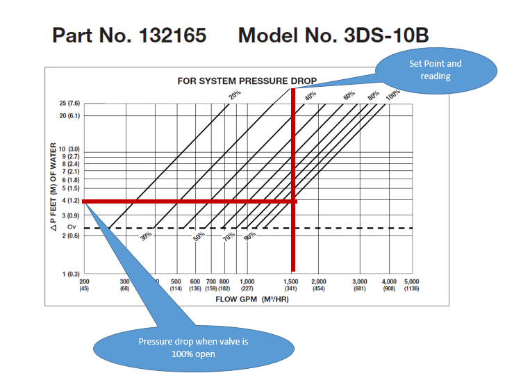
- Using the triple duty flow curves from Bell & Gossett bulletin B-861, determine the pressure drop in feet of head of the valve if it was full open at the design flow rate.
- Subtract the results of step 3 from step 1. This is the excess pump head.
- Subtract the results of step 4 from the design pump head. This is the required pump head with the Triple Duty Valve open.
- Look at the variable speed pump curve and identify a point of the design flow rate at the head from step 5. Identify what speed curve is closest to this point.
- Refer to the drive manufacturers IOM to set the maximum speed of the drive to that speed. Open the Triple Duty Valve 100%.
Let’s Look at an Example
The engineer specified a Bell and Gossett VSX- VSC-5X6X10.5A double suction pump in a closed chilled water system. The scheduled capacity is 1500 GPM at 100 ft. head. They selected the B&G VSC because of the great benefits to the owner, benefits that include silicon carbide unitized seals, ease of service, ANSI/OSHA coupler guard, and a good 15 other reasons. The pump curve selected is shown below.
The balancing contractor completes a proportional balance. The pump discharge has a Bell & Gossett model 3DS-10B – 10” triple duty combination non-slam check, balance, and shut-off valve set at about 30%. What does the contractor do to meet the 2015 Energy Code?
- The contractor reads the pressure differential across the throttled B&G Triple Duty Valve. The difference measured is 15 PSIG (15 PSIG X 2.31 = 35 feet).
- The contractor records the set point of 30%. This is only used to verify the pressure drop and in case you need to return it to design.
- From the chart below we see that when we open this valve to 100%, the pressure drop will be 4 feet.
- Subtract the results of step 3 from step 1 (35 feet – 4 feet = 31 feet, this is the excess head).
- Subtract the results of step 4 from the design pump head (100 feet – 31 feet = 69 feet).
- Look at the variable speed pump curve and identify a point of the design flow rate at the head from step 5. Identify what speed curve is closest to this point (1580 RPM).
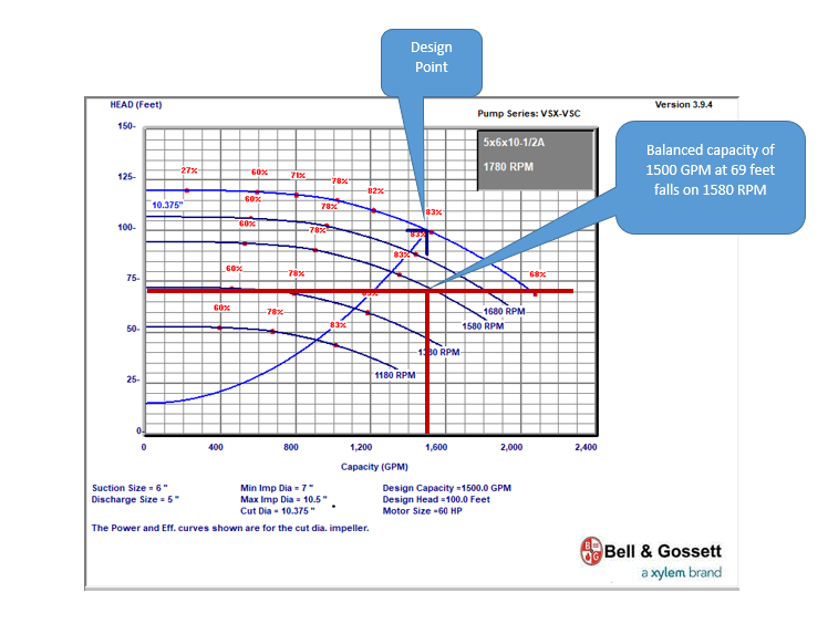
- Refer to the drive manufacturers IOM to set the maximum speed of the drive to that speed. Speed is proportional to hertz. If the drive does not read in RPM, new hertz setting = (1580/1780) X 60. The new hertz maximum is 53 Hz. Open the Triple Duty Valve 100%.
This is a simple way to check the excess pressure drop and set the maximum speed in the drive. This will save a great deal of operating cost.
Operating Cost and Energy Saving
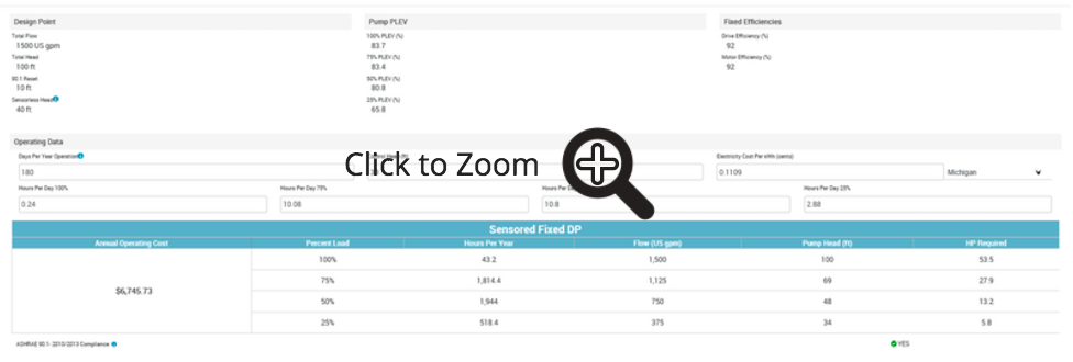
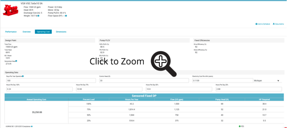
The B&G ESP-Systemwize program will help us determine if the energy savings are great enough to meet the requirements of the Energy Code. Once selected, the operating cost of the pump is simply a few clicks away.
Once we change the maximum speed, the energy cost will drop.
Next week we will look at the same situation with a constant speed pump. We will also look at reasons why it may not be wise to simply allow the controls to reduce the speed instead of applying the steps listed above.

