Bell and Gossett triple duty valves
have, for decades, provided a cost effective way to assure there is a non slam check, balance, and shutoff valve on the discharge of your hydronic pump installation.These valves are used to throttle excess head and, therefore, should not be oversized.
B&G offers these installation friendly valves in traditional full port model (3DS-S) and in a reduced port version (3DS-B). These two models allow a wide range of flow rate and throttling capability while avoiding the costly increases and reducer fittings needed if the valve provided is less than pipe size.
If you specify these valves, I would suggest adding a line to your specification concerning performance: “Valves should be sized with a maximum pressure drop of 5 feet at design flow rate and also allow a pressure drop of 25 feet when throttled.”
When commissioning, the balance contractor completes the proportional balance using the triple duty valve. Then, once complete, a pressure drop read out across the throttled triple duty valve compared to the full open pressure drop will provide the answer to where to set the variable speed drive maximum RPM.
 |
 |
 |
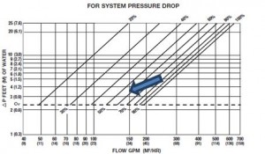
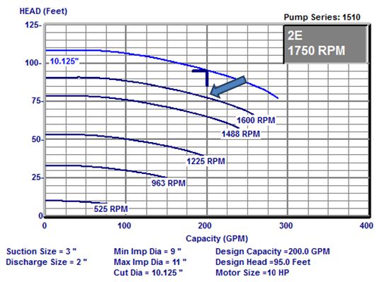
| Figure 1: 3DS-4B curve | Figure 2: installation | Figure 3: 1510-2E variable speed curve |
Example: A hydronic heating system has a B&G 1510-2E with a 10 HP, 460/60/3, 1750 RPM motor and a scheduled capacity of 200 GPM at 95 feet. The engineer included additional head capacity for a future expansion. The balancing contractor, after a proportional balance, reads 19.7 feet across the triple duty valve. What should the VFD maximum speed be set at before opening the triple duty valve?
Solution: At design, the triple duty valve (figure 1) has 2.3 feet pressure drop when full open. Since the pressure drop of the valve throttled is 19.7 feet, the excess head is (19.7-2.3=17.4 feet). The required pump capacity today is (95-17.4=77.6) Now we simply go to the pump curve (figure 2), and find the correct RPM required for today’s capacity. The correct speed is about 1600 RPM. Another way to get the speed is using the first pump affinity law which says (HEAD1/HEAD2)=(RPM1/RPM2)2 or 1581 RPM.
Try that when you only have a butterfly valve on the pump!
Disclaimer: R. L. Deppmann and it’s affiliates can not be held liable for issues caused by use of the information on this page. While the- information comes from many years of experience and can be a valuable tool, it may not take into account special circumstances in your system and we therefore can not take responsibility for actions that result from this information. Please feel free to contact us if you do have any questions.

