The piping at the suction side of the pump is the most important and, for some engineers and designers, the most misunderstood part of hydronic pump piping and trim. The only spoken rule we often hear is five pipe diameters of straight pipe into the suction of the pump. What else does the engineer need to know?
Here at R.L. Deppmann we have often said, “In general, hydronic heating and cooling pumps have a pretty easy duty.” They are not pumping paper pulp with bailing wire pieces. Pumps in hydronic systems pump clear liquid at reasonable pressure and temperatures. Most times the pump enjoys plenty of suction pressure.
Open and Closed Systems
Our closed hydronic systems have a lot of suction pressure caused by the combination of the fill pressure and expansion tank maximum pressure. Open cooling tower systems or open systems lifting from a lake or pond have a separate set of rules. It is critical to follow the manufacturer’s instructions in these applications. Today, we will focus on closed systems.
Before we begin, the standards and guidelines for centrifugal pumps normally start with the Hydraulic Institute (HI). What is this organization?
The Hydraulic Institute
Most of the pump companies you see in the hydronic and plumbing world are members of an organization called the Hydraulic Institute, also referred to as simply, HI. Most HI members are pump companies and their suppliers. Many, but not all, of the pump companies we see in specifications are members of this organization. HI publishes standards for all sorts of pumps. Not just the pumps we use in the simple duty of building heating, cooling, and plumbing, but industrial pumps in, for example, oil refineries and chemical processes. These standards include, for instance, nomenclature standards, testing standards, and installation standards. They set down some ground rules so, for example, your pump curves look similar, and the curves are verified to be correct with a similar set of tests. The Bell & Gossett brand’s parent company, Xylem Inc., is a highly active member. You may be surprised, however, to find pump companies in your specification who are not members!
You can think of the Hydraulic Institute standards just as we think of the American Society of Heating, Refrigeration, and Air Conditioning Engineers (ASHRAE). ASHRAE is a group of member engineers and associated people who volunteer to join standards committees. These committees determine standards from fundamental terms used, to system design ideas, to the concepts used in design, to the testing or commissioning of the systems. HI does the same thing.
You will hear and see the Hydraulic Institute standards or HI often mentioned in the manufacturer’s literature and guide specifications. We will also refer to HI when writing about the installation of pumps.
Pump Suction Components
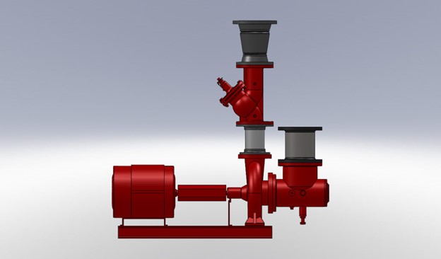
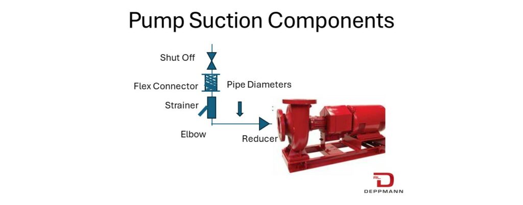
The basic closed system pump suction components are shown above. Most are optional, although most building construction details show them all. We will address them in this order: pipe size, pipe diameters required, strainer, and flexible connector. The shut off valve is required for service and the elbow may be required depending on the header and pump location.
The Hydraulic Institute (HI) and Closed System Pump Pipe Size
The Hydraulic Institute (HI) has several standards for suction piping to a centrifugal pump. In closed systems, HI suggests the suction piping velocity should be limited to 8 feet per second (FPS) at design (HI 9.6.6.3.1).
ASHRAE 90.1 standards and most state energy codes refer to the 90.1-2010 pipe sizing. Hydronic chilled and condenser water pipe sizing for 4400 hours of operation or more results in velocities under the 8 FPS limitations. The pipe sizing for hours of operation less than 4400 will result in higher velocities. Most engineers use the ASHRAE 90.1 chart for all pipe sizing.
The suction piping should be at least as large as the pump suction connection (HI 9.6.6.3.1). This seems simple but we have seen some installations where the suction of the pump was choked down.
Pipe Diameters Required
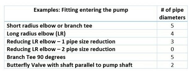
What about the pipe section right at the pump? The most disturbing flow pattern into the pump is a “piping generated swirl.” Swirling occurs as the water flows through a fitting, causing the water in the pipe to change all or part of its direction. In hydronic installations, this fitting is an elbow. Bell & Gossett suggests 5 pipe diameters or the use of a Bell & Gossett Suction Diffuser Plus. A reducing elbow requires less straight pipe then a straight elbow. Let’s look at a few examples from HI.
So why does a reducing elbow require less diameters than a straight elbow? As the area is reduced into the suction of the pump, the swirling is reduced. This list above is not exhaustive. There are many more situations in the HI table of fittings.
The Strainer
We will address the suction strainer for closed systems. Suction side strainers are no friend to the centrifugal pump. They may clog up and become a large pressure drop device at the pump suction. This can lead to noise and pump damage. That said, they are a normal part of pump suction trim.
The strainer might be a traditional old style wye strainer or even a higher efficient strainer like the Metraflex LPD. It may also be a basket style strainer. In addition to body style, they also have different screen sizes. Strainers may come with different size holes or mesh or perf. You can see an example of this in an article I published on steam strainers.
The thing about a strainer is that it will clog up. When it clogs up, the pressure at the pump suction will drop. If the strainer plugs up too much, the pressure in the pump suction may drop down so low that the water turns to vapor. This whole story is the story of net positive suction head (NPSH) and the NPSHR “required” by the pump.
Strainers on pump suctions protect the pump from larger items that could damage the impeller. In general, there is no need to “strain” all the particulates out of the water to protect the pump. The smaller the holes in the strainer, the faster they plug. Most pump strainers have 1/8” holes in them. This is plenty big enough to catch the things that may damage a pump. This is what I recommend you use. It is also standard on most strainers used for water service in hydronic applications.
If you need a finer mesh strainer for a device downstream, install a strainer at the device. For example, there are many chillers available that use brazed plate heat exchangers similar to the B&G BPX. The chiller may require a 20-mesh strainer to protect the small openings in the chiller heat exchanger. Well, a 20-mesh screen has a hole that is 0.033 inches. This is quite a sieve compared with the 0.125-inch pump strainer. If that fine mesh strainer is on the pump, there could be problems.
There are several pump suction options with strainers. The Suction Diffuser Fittings in Hydronic Pump Piping and Trim is one that eliminates the strainer, elbow, and, at times, the reducer.
Flexible Connectors
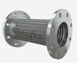
Flexible connectors are a normal part of larger pump details. There are a number of types of connectors, and we can address that in a later blog. When we are talking about pump suction piping, there is a product you may want to know about. We represent Metraflex in our territory. Metraflex has a Suction Diffuser Flex, which may be a great option if you are not using a suction diffuser elbow. Just another tool in the toolbox.
Hopefully this blog helped you with the pump suction piping components and pipe sizing in closed hydronic heating and cooling systems.

