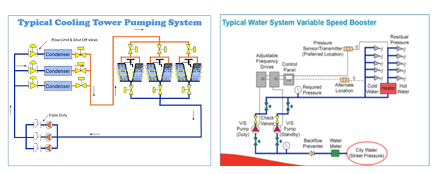
System curves give insight into energy analysis, pump operation, and control setting analysis. Unlike closed hydronic systems, open systems rarely have a system curve that starts at zero flow and head. Whether your system is an open cooling tower, plumbing pressure booster, or even a swimming pool, the engineer needs to understand the open system curve. Today, we look at developing the open system curve.
System Curves Defined
A system curve is a representation of the relationship between flow rate and pump head. As the centrifugal pump develops head pressure, what is the expected resultant flow? We introduced these curves for closed hydronic systems in previous R. L. Deppmann Monday Morning Minutes, Closed System Curves in HVAC Hydronic Systems.
These closed system curves started at zero GPM and zero feet of head. Any pressure differential caused by the pump would result in an expected flow rate. Open systems are different. Let’s use two examples to show how the system curve varies in an open system.
Hydronic Open Cooling Tower System Curves
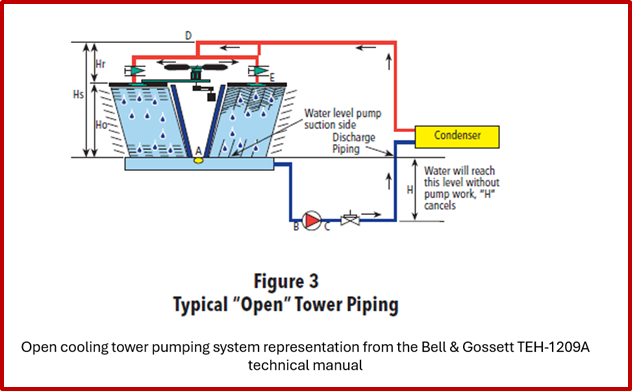
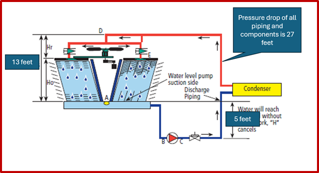
Look at the cooling tower pumping system sketch shown above. When the pump is off, there is water in the tower basin. That water will fall into the piping system and rise on the pump discharge to a level shown as “H.” This example will assume “H” is 5 feet. Assume for a moment that the elevation of the cooling tower and the small supply piping (shown as Hs) is 13 feet.
Let’s start the variable speed pump and say the pump is producing 5 feet of head. If the gauges read in feet of water head, the suction gauge would read 5 feet and the discharge would be 10 feet. Look at the elevation called Hs. If the pump was creating 5 feet of head, all we would be doing is raising the water level 5 feet into the piping shown in red.
In fact, no drop of water would enter the cooling tower until the pump produced a little bit over 13 feet of differential. All the pump head above 13 feet would cause flow but until we get to 13 feet, there is no flow.
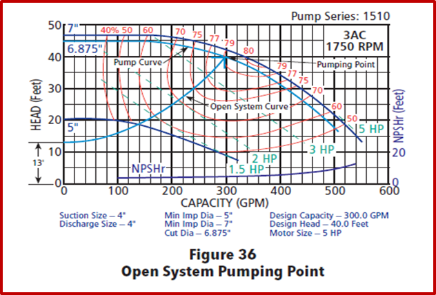
Now let’s assume that the pressure drop through the condenser, piping, and valves was 27 feet. The pump head required would be 27 feet PLUS THE LIFT. The lift is 13 feet. So, the required pump head at the design flow rate would be 27 feet plus 13 feet, or 40 feet. Now, let’s look at the system curve.
The system curve shows that flow rate does not start at zero feet of head. We must lift the water 13 feet and then the flow starts. From there the curve will follow the second pump affinity law. After the lift, the curve looks just like the closed system curve.
Plumbing Pressure Booster System Curve
Now, we look at an example that has more numbers. Engineers, put your thinking caps on!
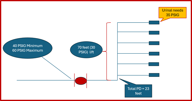
Building pressure boosters pumping systems are installed when the minimum municipal water pressure will be less than that required for the building. Here is an example system.
Assume the water flow rate required is 300 GPM. The pump discharge pressure required would be the friction loss of 23 feet or 10 PSIG plus the lift or elevation of 30 PSIG plus the fixture pressure required of 35 PSIG. This is 10+30+35 = 75 PSIG.
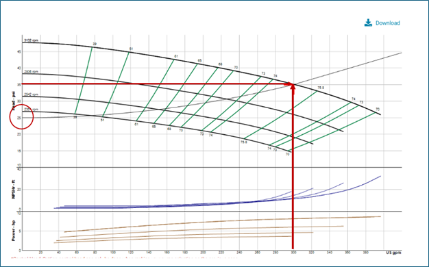
The city water pressure can drop as low as 40 PSIG at the pump suction. We need a pump! The pump will have to produce the required pressure minus the minimum pressure from the city. The pump head at 300 GPM will be 75 PSIG minus 40 PSIG from the city, or 35 PSIG at 300 GPM.
It is important to note that at times the city pressure is 60 PSIG. At those times, the pump will only need to produce 75 PSIG minus 60 PSIG from the city, or 15 PSIG. Perfect for variable speed energy savings. We are just looking at the design conditions right now.
Look at the system curve numbers slowly. The pump discharge required is 75 PSIG. Of that, the elevation of 30 PSIG remains constant regardless of flow rate. The fixture requirement of 35 PSIG is required even if there is only one urinal in use. This 35 PSIG is the required pressure to make the system work. It is just like the control head in our previous closed system blog, What is Control Head in Hydronic Variable Speed Pumping? The fixed open system “control head” is 30+35 or 65 PSIG. The pump discharge must have 65 PSIG whether the flow rate is 300 GPM or 3 GPM. The control head is 65 PSIG. The city will provide a minimum of 40 PSIG. So, the pump must produce 65-40=25 PSIG plus the friction loss of 10 PSIG. The only variable head loss is friction.
We will select a pump for 300 GPM at 75-40=35 PSIG. The B&G ESP Systemwize is great for the selection. It will allow us to enter the pump head in PSIG. It will also allow us to enter the fixed pressure, which in this case is the elevation and the minimum urinal pressure. Here is the curve:
We showed a single pump for this plumbing system. We would recommend two pumps at 150 GPM since plumbing systems rarely, if ever, meet the design flow rate. For more information about B&G pressure boosters you may visit of selector widget on our website at Pressure Booster Systems.
Next week, we will circle back to pump suction piping for open cooling tower pumps.

