Printer Friendly (PDF)
 Most centrifugal pumps in heating and cooling systems have some oversizing in the head calculation. Once the HVAC hydronic system is proportionally balanced per ASHRAE 90.1 energy standards, all this extra head is known. The VFD speed may be dialed down to save energy and complete the balance. Just what are the steps required to complete this valuable process?
The first article in this series introduced a short explanation of proportional balance. The second article addressed the impeller trimming of constant speed pumps. Today, we look at the reduction of speed to simulate impeller trimming on centrifugal pumps with a variable speed drive.
ASHRAE 90.1 – 2013 and Speed Reduction
ASHRAE 90.1 – 2013 is the standard used by many States for the State Energy Code. Section 6.7.2.3.3 states the system shall be proportionally balanced and then, for variable speed pumps over 10 HP, the speed adjusted to meet the design requirements. The exception is stated as “when throttling results in no greater than 5% of the nameplate horsepower draw, or 3 hp, whichever is greater, above that required if the impeller was trimmed”.
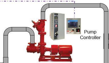
Since section 6.5.4.2 defines the variable flow systems with variable speed pumps as the required pump control in pumps over 10 HP, this blog is fitting.
Centrifugal Pumps Over-heading
In part one of this series, Proportional Hydronic System Balance Process, we used an example Bell & Gossett pump. Once the hydronic system balance was complete, the pump was flowing more gallons per minute (GPM) than scheduled. Look at the variable speed pump curve.
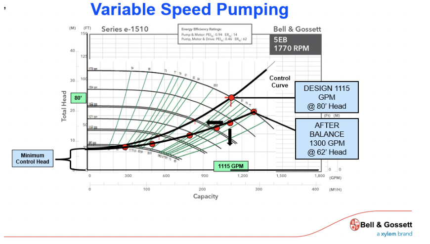
We see that the original specified 80 feet of head was generous. After the proportional balance, the system only requires 62 feet of head, at 1300 GPM, including the 24 feet of control head. Why not break the steps down based on two different installations?
One installation assumes the availability of a B&G triple duty valve or other balance valve with pressure ports for reading pressure drop. Although the need for a discharge balance valve is diminished with variable speed drives, it can be a valuable tool. In this case the balance contractor used the triple duty as the throttling means during the balance. The second installation assumes no balance valve on the discharge of the pumps. We’ll cover this topic in the next blog.
Steps for Setting the Pump Speed to the Balanced Flow and Head -Systems with a Pump Discharge Balance Valve
Each step below will follow with the step in our example system.
- 1. Read out the pump after the proportional system balance is complete.
- Read out the pump suction and discharge pressures and convert to pump differential in feet of head. Use the correct multipliers if glycols are being used. We use charts provided by a supplier we trust, “Go Glycol Pros”. The charts are located at “Centrifugal Pump Gauge Readout Corrections for Hydronic Glycol Systems. Record all readings, not just the differential.
- In our Example system:Suction is 10 PSIG. The discharge is 37 PSIG. The difference is 27 PSIG or 62 feet. Fluid is water at 70 degrees F.
- Read out the pump suction and discharge pressures and convert to pump differential in feet of head. Use the correct multipliers if glycols are being used. We use charts provided by a supplier we trust, “Go Glycol Pros”. The charts are located at “Centrifugal Pump Gauge Readout Corrections for Hydronic Glycol Systems. Record all readings, not just the differential.
- 2. Locate the pump curve submittal and identify the design RPM on the submittal. This would be the maximum speed. Set the drive at this speed. Most pumps will be throttled lower than this speed after the balance is complete. Please note that the expected and scheduled pump speed at design may be different than the motor RPM. Variable speed selections may use a larger impeller and trim to design using the pump speed. Record this as the design RPM.
- Example: This example has a submitted pump with the operating speed the same as the motor speed.
- 3. Throttle the pump discharge balance valve until the pump differential is set for the design flow. Record the readings. Read the differential across the throttled valve. Record the throttled discharge valve differential and the setting of the valve.
- 1085 Example: This pump has a B&G 3DS-8S full port triple duty valve with a full open CV of 1085. The pump was throttled until the suction reading was 11 PSIG and the discharge was 45 PSIG. This is about 80 feet of head. The triple-duty valve was throttled and the differential across the valve was 31 feet.
- 4. We will compare the throttled balance valve pressure drop compared with the full open pressure drop at the design flow rate. The difference will be subtracted from the design pump head for the new condition at a lower speed.
- 5. Open the pump discharge valve 100%. Reduce the speed on the drive to that found in step 4. Verify and tweak until the pump differential matches the values obtained in step 4. Record the speed.
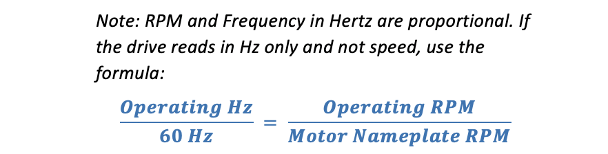
- Example: The new condition is 1115 GPM at 52 feet. The new RPM at maximum demand will be 1550 RPM. This is converted to 53 Hz.
- 6. Lock this speed as the maximum RPM or Hertz in the drive and note this action in the report. See our previous R. L. Deppmann Monday Morning Minutes “Adjusting a Variable Frequency Drive (VFD) to Over Speed HVAC Centrifugal Pumps” for instructions for locking in a different maximum speed.
Next week, the R. L. Deppmann Monday Morning Minutes will explain the process for doing this pump balance if there is no discharge balance valve.
1 ANSI/ASHRAE/IES Standard 90.1-2013 page 62.