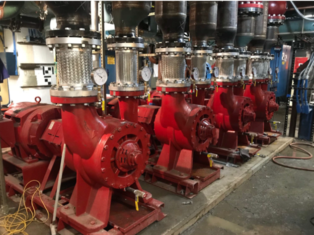
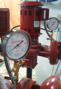
 The proper readout of a centrifugal pump in a hydronic system is important. Pump readout will determine the head pressure the pump is developing which will lead you to the flow rate and point of operation on the pump curve. Understanding where the pump is operating will be useful in troubleshooting pump and system issues. But first, how do you read out a centrifugal pump?
Preparation Required to Read Out a Centrifugal Pump
Attempting to read out a centrifugal pump without proper preparation can be futile and dangerous. The very first thing you need to do is gather the proper safety equipment including safety glasses, safety gloves, and other equipment needed based on the application. Never have loose or hanging clothing around rotating equipment.
You also need to know the brand and model of the pump you will be reading. The link above may help if you have an existing B&G pump to identify.
Once you have the brand and model you must contact the pump representative for the proper pump curve at the motor speed of the pump. You will also ask for the operation instructions from the manufacturer for the important safety information to read and follow. If the pump is variable speed, make sure you ask for the variable speed curves.
Pressure Gauge Location on Pumps
We will assume the pressure gauge or gauges are already installed. They should be located on the suction and discharge taps of the pump. If there are no tappings, the gauges should be located on the pipe right at the pump. They should not be located on the pipe past check or balance valves or before strainers. These devices will affect the readings.
Remember to be careful. The fluids and pump may be hot. The pump is a rotating piece of equipment.
Step 1: Read the Static Pressure
Before the pump is even on you can gain knowledge. Read the static pressure. This will tell you whether the system has water all the way to the top. Learn more about this in our Expansion & Compression Tanks in Hydronic Systems: Initial or Cold Fill Pressure.
Once we know the static or fill pressure is correct at the pump, we can move on to step two.
Step 2: Creating the Design Conditions
Have the pumps operating in the full heat or cool valve positions. Normally you are trying to see what the pump is doing at the design condition. You must first have the design condition. The design normally means all two-way valves open to the full coil position in a closed hydronic system. You may turn off the boilers or chillers to prevent unwanted temperatures unless that causes a freeze possibility or owner problems.
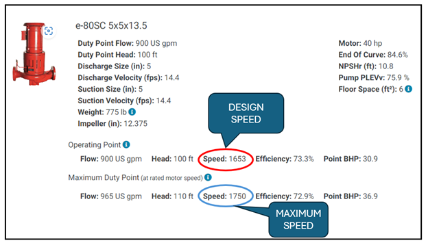
The pumps should be operating at the full speed determined during the commissioning. A variable speed pump may operate at a maximum speed which is less than the motor speed. In addition, the balance contractor may have set the variable speed drives (VFD) at a lower maximum speed to reduce extra pump head used as a safety factor.
The pump may have a discharge balance valve or triple duty valve. These may be throttled to achieve the same head reduction just mentioned. Note the valve position and do not change the setting.
The only reason to change the maximum speed or balance valve position is to verify how much “more” a pump can do. It is critical to be able to return the system back to where it was before you started the pump readout.
Step 3: Shut Off Reading or Verifying the Correct Impeller Diameter at the Correct Speed
One flow rate we can always guarantee is the zero GPM flow rate. We will do this by closing the discharge valve to stop the flow rate. This is a shut off reading. Three things you must be aware of before you do this.
- Never close the discharge of a positive displacement pump. These articles are all about centrifugal pumps.
- If the centrifugal pump is over 75 HP or a multistage pump, verify with the manufacturer that the pump can be read at shutoff. Most can but it is good to check.
- Watch for heat buildup while taking a shutoff reading. Shut off conditions should happen in seconds not minutes.
Slowly close the discharge valve. Take a reading of the discharge pressure. Take a reading of the suction pressure. Open the discharge valve.
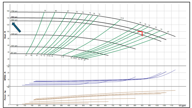
Example: Assume a closed chilled water system. We shut the chillers off and drove the two-way valves fully open. The B&G model e80SC pump has a design speed of 1653 RPM. We found the balance contractor set the maximum speed at 1600 RPM. We set the VFD at 1600 RPM and read the shutoff head. We opened the discharge valve before doing the math.
Discharge Reading: 67 PSIG and Suction Reading: 11 PSIG
The difference is 67 – 11 = 56 PSIG. The shut off head is 56 PSIG X 2.31 = 129 feet.
It looks like we have the right impeller diameter and the right speed. The pump shut off head is correct.
Step 4: Operating Reading
With the discharge service valve open and the pump flowing water at 1600 RPM, we now read the operating condition.
Example: The pump above had the following readings.
Discharge Reading: 49 PSIG and Suction Reading: 10 PSIG
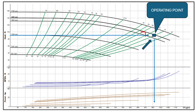
The difference is 49 – 10 = 39 PSIG. The operating head is 39 PSIG X 2.31 = 90 feet.
Look at the pump curve again.
We read 90 feet on the vertical axis and drew a line across until we intersected the 1600 RPM curve. The flow rate is about 960 GPM. This is above the 900 GPM design but within a 10% tolerance.
Step 5: Return the System to Proper Operation
This may seem silly to mention but put the system back in automatic control with the chillers back in their operable position.
Using a Single Pressure Gauge Will Improve Accuracy
We mentioned the importance of the pressure gauge location in pump readout. There are many choices for pressure gauges. The series on cooling tower pumps suggested a compound gauge on the pump suction. That gauge will read vacuum and pressure. Visit Pressure Gauges for HVAC & Plumbing Systems for more about pressure gauge specification.
A previous R. L. Deppmann Monday Morning Minutes, Determining Pump Operating Condition Using the Single Gauge Method, explains how and why to use a single pressure gauge for pump readout.
A single pressure gauge should be mounted with connections to the pump discharge tapping and the pump suction tapping. The gauge should have an isolation valve on each of those connection pipes. Watch the video above to learn more.
Special Conditions
The accuracy of the readings is critical. Here are articles about special situations and fluids:
- HVAC Hydronic System: Parallel Pump Operation and Curves
- Centrifugal Pump Gauge Readout Corrections
- Centrifugal Pump Gauge: Balancing for Glycol Temperature
- Centrifugal Pump Gauge Readout: Velocity Head Corrections
- Preso Ellipse Flow Meters for HVAC Hydronic Mains
Next week we will look at more about the parts and pieces around a pump in a hydronic heating or cooling system.

