When there is no hydronic pump discharge balance valve, the variable frequency drive (VFD) is an important part of the balance procedure. How does the balance contractor use the variable frequency drive (VFD) to balance the pump to the design flow rate?
The first article in this series introduced a short explanation of proportional balance. The second article addressed the impeller trimming of constant speed pumps. The third article used the variable speed pump discharge triple duty valve to assist in the determination of the new lower speed. Today, we look at the procedures to set the speed of the drive with no available discharge balance valve.
Using the Variable Speed Drive (VFD) During Balance
In previous articles, the balance contractor throttled the discharge balance valve during the balance. Now we have a system with no discharge balance valve. The balance procedure step of starting with a throttled pump is still valid.
- The contractor reads out the pump differential of the pump in the unbalanced system.
- Throttles the speed using the VFD. Checking the differential against the appropriate speed curve until the flow is 10% -15% above the design. This may involve several readings.
- Continues the proportional balance as described in Hydronic Pump Energy Savings and Proportional Balancing Technique.
- If at any time the flow rate is too low to achieve the proportional flow (cannot get the flow with the balance valve wide open), You must raise the speed. I would suggest raising it for an additional 5% speed if you are close to the end of the sub-circuit and 10% if you are early in the balance.
- Now you must go back to the previous balance valve and identify a new proportion or percent of design flow. This is what you will use for the continuation of the circuit.
- Continue the rest of the balance steps.
Centrifugal Pump Over-heading Example
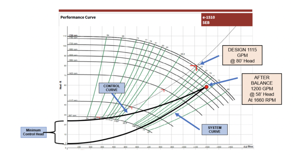
In the first three parts of this series we used an example Bell & Gossett pump. Once the hydronic system balance was complete, the pump was flowing more gallons per minute (GPM) than scheduled. Since we are throttling the speed as we go. The pump will be closer to the design flow rate but will still need to be set to design. Look at the variable speed pump curve.
We see that the original specified 80 feet of head was generous. During the proportional balance, the pump speed was reduced to 1660 RPM. We see that the flow rate is still slightly higher than the design. The flow rate is within 10% of design, some balancers would leave it there. If you want to throttle to the exact design flow rate, the steps are simple.
The First Affinity Law and System Curve vs. the Control Curve
The first affinity law states that:
GPM varies proportionally to RPM. This law and the second law (head varies as the square of GPM) will create the system curve shown above. The control curve has a fixed control head. The control head in this example is 24 feet. This changes the curve slightly as shown above. Why am I saying this and why is this important?
The control head is like the lift in an open system. We want the control head to be maintained at all flow rates. Read my explanation of the open system curve in our Open Cooling Tower System Pumps – Balancing the Pump Using a Drive.
If I use the formula above to set the speed at 1115 GPM, the answer will follow the system curve, not the control curve. This RPM is close enough if the flow rate after system balance is within 15% of the design flow rate. If the difference is greater than 15%, you should plot a new control curve on the existing pump curve to find the speed.
Steps for Setting the Pump Speed to the Balanced Flow and Head -Systems without a Pump Discharge Balance Valve
- Read out the pump after the proportional system balance is complete.
- Read out the pump suction and discharge pressures at the current speed and convert to pump differential in feet of head. Use the correction multipliers if glycols are being used. We use charts provided by a supplier we trust, “Go Glycol Pros”. The charts are located at “Centrifugal Pump Gauge Readout Corrections for Hydronic Glycol Systems.” Record all readings, not just the differential. Record the current RPM of the drive.
- If the flow rate in step 1 is within 15% of the design flow rate:
- Take the percent of design flow rate to the current flow rate, (GPM at design)/ (GPM currently reading). Multiply that number times the current throttled speed. This is the new speed to set the drive.
- In our example: (1115/1200) X 1660 = 1542 RPM
- If the flow rate in step 1 is not within 15% of the design flow rate:
- Use the B&G esp-Systemwize program or contact your local representative. Create a control curve using the same pump and impeller size with the flow rate and head equal to what you had in step 1. Read the new RPM at the design flow rate. This is the new speed to set the drive.
- In our example: The control head is 24 feet. The new speed with a new curve would be 1575 RPM. I will show you how we arrived at this in the next Monday Morning Minutes.
- Lock this speed as the maximum RPM or Hertz in the drive and note this action in the report. See our previousR. L. Deppmann Monday Morning Minutes “Adjusting a Variable Frequency Drive (VFD) to Over Speed a HVAC Centrifugal Pump” for instructions for locking in a different maximum speed.
- Use the B&G esp-Systemwize program or contact your local representative. Create a control curve using the same pump and impeller size with the flow rate and head equal to what you had in step 1. Read the new RPM at the design flow rate. This is the new speed to set the drive.
- Take the percent of design flow rate to the current flow rate, (GPM at design)/ (GPM currently reading). Multiply that number times the current throttled speed. This is the new speed to set the drive.
Next week, the R. L. Deppmann Monday Morning Minutes will show the process of finding the right curve in the Bell & Gossett esp-Systemwize program using the example shown above.


