We continue to look at air issues and swirling issues in this third segment of cooling tower pump suction piping. We also provide you with the answers to last week’s design quiz. We will start with those answers in this week’s R. L. Deppmann Monday Morning Minutes.
Quiz Answers from Last Week’s Problem
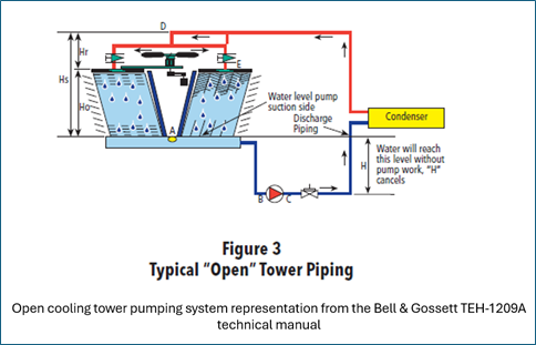
Last week in our Open Cooling Tower Pump Suction Piping Part 2, we offered a “homework” example problem, asking five questions. Here are the solutions to those five questions:
1. What is the NPSH required by the pump?
Do not forget the safety factor of 1.5 suggested in the blog link above.
Answer: 22.5 feet or 21.9 feet
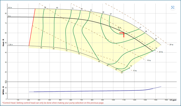
a. Look at the curve above at 1100 GPM and read up to the blue NPSHr curve, then go across and the NPSHr is shown as 15. There is a recommended 1.5 safety factor so 15 x 1.5 gives us the answer of 22.5 feet.
b. You could also open esp-Systemwize from Bell & Gossett (B&G) and select the 5BD constant speed pump. When you click on it for details, B&G tells you the NPSHr is 14.6 so 14.6 x 1.5= 21.9 feet.
c. Either answer is close enough for our purposes with our 1.5 safety factor.
2. What is the velocity in the suction pipe in FPS?
Answer: 7.06
a. You were given that the suction pipe was 8” steel. If you open the B&G System Syzer on your computer, the answer is easy to find. Click the flow/pressure drop tab and enter the 1100 GPM and select 8” pipe. Note: I changed the far right from 60⁰F water to 85⁰F water. Won’t make much difference but it will have a small effect later.
b. Note that this is over a suggested 5 FPS but under the HI maximum of 8 FPS. We were given an 8” pipe but 10” pipe that would drop the suction velocity to under 5 FPS. Visit Open Cooling Tower Pump Suction Piping Part 1 to read more.
3. What is the pressure drop in the piping at 1100 GPM? HINT: Use the “Help with total equivalent length (T.E.L.)” button on the Length/Pressure Drop tab.
Answer: About 8 feet (7.93’)
a. I will show some screens from the System Syzer for this one. You may use another method and the answer will vary slightly. We went to the Length/Pressure Drop tab. We then entered the 30 feet of pipe we were given in the problem. Next, we will check the “Help with TEL” box.
b. We enter the 4 elbows, butterfly, and the reducer from the 8” pipe to the 6” suction. Include the strainer by changing to PSIG and entering the given pressure drop.
4. What is the NPSH available to the pump? Do not forget the elevation.
Answer 25.6 feet
a. Now we click on the NPSHa, NPSH available, tab and it shows 24.7 feet; but you must enter the water height above the pump and change the elevation above sea level. We are given 2 feet above the pump suction as the minimum water level. The elevation given is 1000 feet above sea level.
b. Interesting to note: if you forget the elevation, the NPSHa is shown as 26.7 feet. If you also forget the slight temperature change, the NPSHa will be shown as 27.3 feet.
5. Can you use this pump in this application?
Answer: Yes
a. From question 1, we know that the pump needs about 22.5 feet of absolute pressure at the suction. From question 4, we see the piping will give us 25.6 feet of absolute pressure. We are comfortable with this selection.
Three comments for the engineer:
- First: There are only a few feet difference between the available and required NPSH. Do you really want the contractor to try to figure out how to pipe this? This is a time to detail the piping you want to see on the project.
- Second: If you used 10” pipe, the NPSHa would rise to 27.7 feet.
- Third: We would normally want that tower elevated more than the 2 feet shown in the example. Lifting it up by six feet makes the NPSH available much better and reduces the chance of air issues.
More Comments About Air Suction Piping
The astute engineer will recognize something about the NPSH available in the example above. We have 25.6 feet of absolute pressure at the pump suction. On a compound gauge, this absolute pressure will result in a negative gauge pressure or a vacuum. It is alright to have a vacuum on the pump suction. You should always have compound gauges on the inlet of cooling tower pumps — it can tell you a lot.
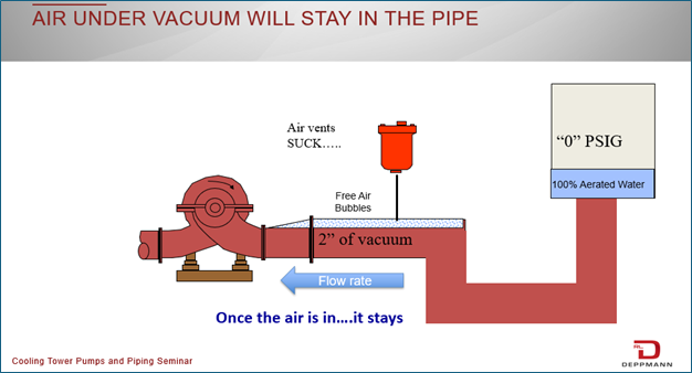
You must also recognize that an automatic air vent on the suction of the pump will be operating in reverse — it will be sucking air into the system rather than venting. Any vent on the suction should have a quality check valve in the discharge of the air vent. This way, you will not be sucking air into the inlet.
Avoid air pockets in the cooling tower pump suction pipe. Look at the drawing above from one of our training classes. We see this too many times. The piping drops from the tower but lifts back up into the pump. The eccentric reducer at the pump suction will cause a pocket of air. This will reduce the area available in the pipe for water to flow and increase pressure drop. We have a combination of air issues and pressure drop issues attacking the pump.
Try to avoid these up and down air pockets in your design. Turning the eccentric reducer with the flat on the top would also avoid an air pocket in this example.
Flow Patterns Entering the Cooling Tower Pump
The last thing a pump manufacturer wants to see is a swirling flow pattern into a pump with little suction pressure. It is a recipe for noise, frequent maintenance, vibration, cavitation, reduced flow, and pump damage.
The “rule of thumb” in any pump suction pipe is five pipe diameters of straight pipe entering the pump. There are times when the Hydraulic Institute recommends even more than five pipe diameters. There are times when they allow less than the five pipe diameters. Work with your B&G representative to see the appropriate piping for your system.
We rarely see five pipe diameters of straight pipe in a cooling tower application. Two solutions that R. L. Deppmann represents is the Bell & Gossett Suction Diffuser Plus and the Metraflex Suction Diffuser Flex – Energy Efficient Pump Connector. Both reduce the pipe diameters required on the pump suction.
Cooling tower pump suction piping is one of the most complicated and misunderstood subjects in hydronic cooling systems. Contact our R. L. Deppmann engineering team for more design assistance and the classes we offer.


