Printer Friendly (PDF)
 Parallel pumping in hydronic systems can save energy and construction capital costs. Today we continue the series on parallel pumping where we look at the operation and curves of parallel pumps.
Parallel Pump Curves
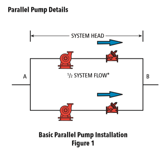
If we look at the simple pump schematic here, there are two 50% pumps. Each pump will operate on its pump curve. Let’s select an example staying with the Grand Rapids, Michigan heating system weather BIN data we introduced in part 1 of the series. Let’s assume a building has a 10 million BTUH load with a 40°F ΔT at design. The design flow rate is 500 GPM and we will use 60 feet of head. The system will use three Aerco BMK-4000 condensing fire tube boilers which will allow us to use primary variable pumping. The minimum flow through a single boiler is 37 GPM.
The pump curves are developed by using the ESP-Systemwize selection program. You enter the total design flow conditions of 500 GPM at 60 feet. Instead of the default, which is one pump in parallel, you now select two pumps.
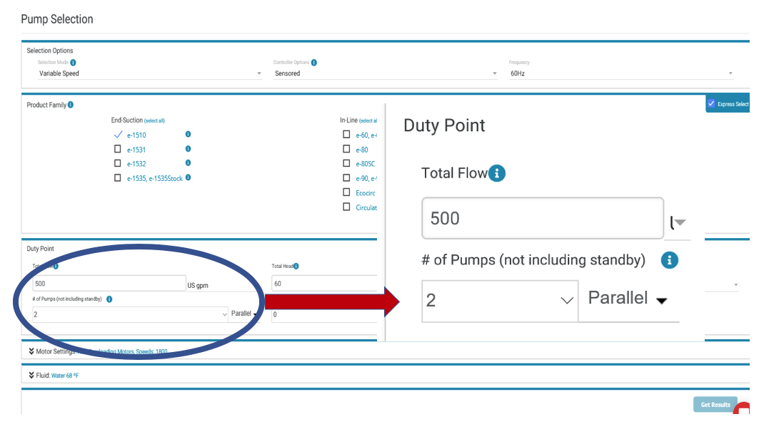
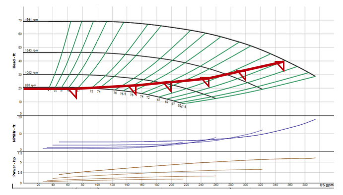
We will select the two e-1510-2.5BB pumps in parallel. The parallel pump curve looks like this.
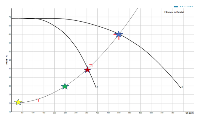
I am showing it in constant speed to keep the graph from becoming too cluttered. This pumping system is very interesting. The two pumps will operate in parallel from design of 500 GPM (blue star) down to 350 GPM (the red star).
Both pumps will operate at the design flow and head conditions at 1641 RPM. As the 2-way control valves close, the speed will drop. When the system capacity drops to 175 GPM each pump at 40’, the speed will be about 1300 RPM. At this point, a single pump can do the job so we will shut one pump off. The operating pump will speed up and run out on the curve to the 350 GPM, 175 GPM X 2, at 40’ and will be back to 1641 RPM. This is called the staging point.
In this system, a single pump will operate from the minimum flow of 37 GPM all the way to 350 GPM.
The pump will operate out on its curve past the 250 GPM design point and move out to 350 GPM.
Here is what the single curve looks like in variable speed.
So why should we consider variable speed? We ran the energy analysis for boiler operation on the AERCO energy program. In our example for Grand Rapids, the times when a single pump will operate is shown below.
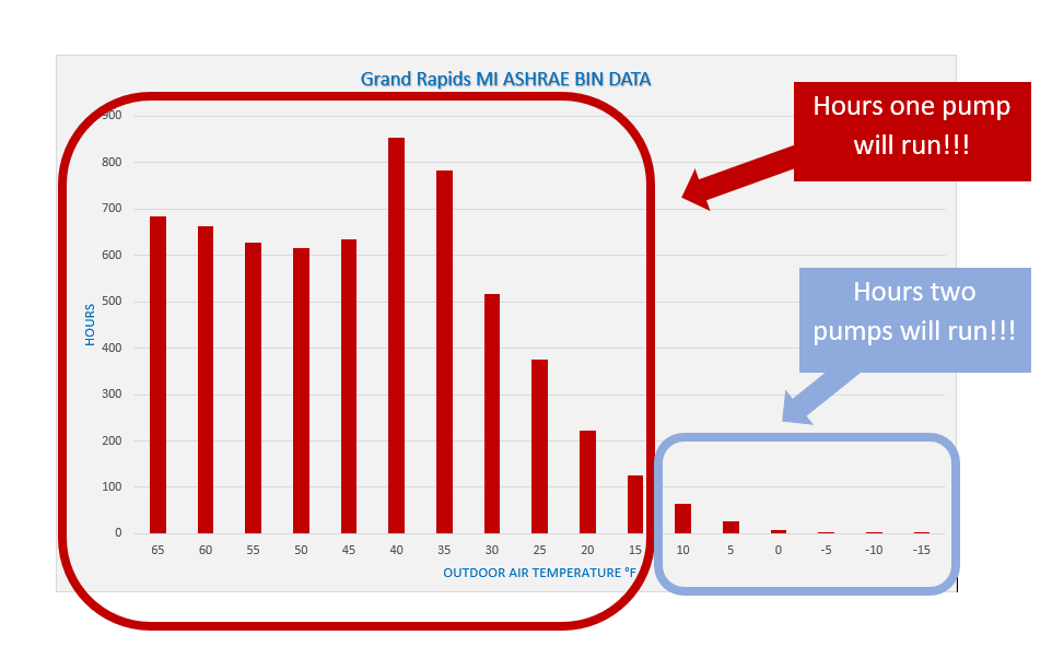
Gil Carlson, the author of most of the B&G engineering design manual, said, “No pump saves more energy than a pump that is off.” Parallel pumping can save energy and it definitely saves on first cost.
The point when pumps turn on and off is called the staging point. How do we make this happen? What controls are needed? We will address this in the next R. L. Deppmann Monday Morning Minutes.
HVAC Hydronic Series:
Article 1: What is parallel pumping and why do it?
Article 2: Selecting parallel pumps and the curve
Article 3: Controlling parallel variable speed pumps
Article 4: Parallel pumping and standby capacity
Article 5: Parallel pumping and cost
Article 6: Parallel pumping specifications