Parallel pumping is a preferred method of design for many hydronic and plumbing system applications. Today we describe five examples when you may want to examine a parallel solution. We also look at the staging of parallel pumps and offer some tips.
Parallel Pump Operation
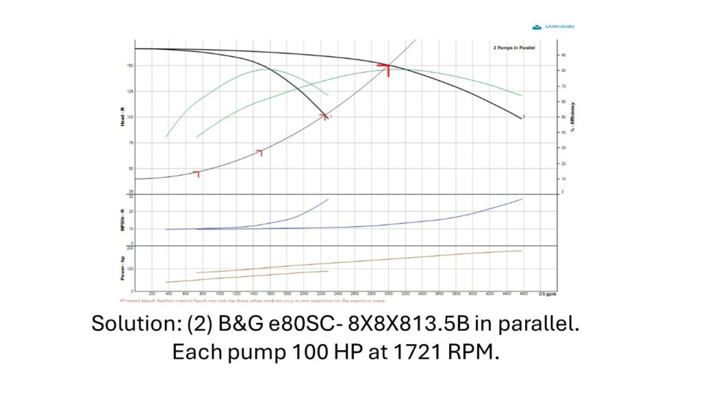
One of the advantages of parallel pumping is the ability to shut one of the pumps off and operate with one pump most of the season. Our last blog, Centrifugal Pumps – Parallel Pumping, showed how the parallel pump curve is created. When a pump stages off, the operation of the remaining pump or pumps will move out on their curves to a higher flow. This flow is determined by the system curve.
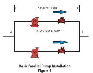
The curve shown above is an example. When a single pump is operating, the system curve shows the pump will flow much more than 50% of the design flow rate. Before we begin you may want to review the definition of parallel pumps in the link above.
Why Use Parallel Pumping?
A single variable speed pump selected for the total design flow rate is simple and saves energy. Why bother with the complexity of parallel pumping and staging of pumps on and off? There are situations where a single pump operating may not be the best choice. Here are five examples:
-
Standby Capacity Without a Standby Pump
When a parallel pump is turned off or destaged, the operating pumps will run out on their curves. They will supply a higher flow rate than if they were selected for at design. It will not be 100% but it will be significant. If your client does not require 100% standby and the project budget is important, parallel pumping may be a solution.
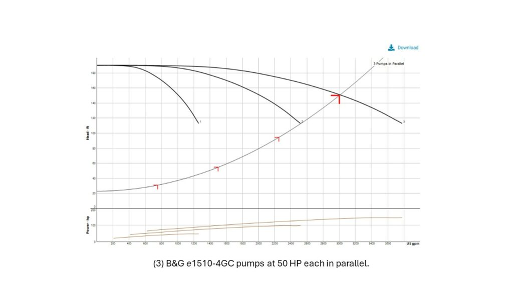
Look at the three-pump system shown above. If a pump is offline, the remaining two pumps will produce 84% of the design flow rate. Remember that in hydronic systems, an 84% flow rate provides more heat transfer than 84%. Visit these blogs for more on this subject:
-
Project First Cost Savings
When you select parallel pumps, they are smaller. The flow rate is a fraction of the total system design flow rate. Each pump will, normally, end up being smaller with a smaller horsepower. Smaller pumps mean less cost. In addition, the piping components of each pump are sized for a lower flow rate and a smaller pipe size. Smaller pipes mean less cost.
-
Operation Near Design Flow Rate May Never Happen
The perfect example of this is plumbing pressure boosters. Every plumbing engineer knows that the standards used in determining a cold-water flow rate are very safe. Rarely will there be a standby pump on a multiple pump pressure booster. The two, three or four pumps are staged in parallel with all the pumps designed to operate. If your system design is too safe, parallel pumping may be an answer.
-
Future Additions to the System
The owner expects future additions but is not clear when and even if the addition will happen. Engineers may hear this more than one would think. Design the system for parallel pumping in the future. Leave the room and place the housekeeping pad for a future pump. Use a single pump now with a standby. Add another pump in the future.
-
System Minimum Flow is Very Low
Most centrifugal pumps have a required minimum flow rate. The minimum flow rate gets larger as the pump gets larger. The three-pump variable speed system shown above is an example. A single 3000 GPM pump selection would have a minimum flow rate required of about 400 GPM at the minimum speed. The minimum flow rate at minimum speed of the three-pump parallel design would drop to under 100 GPM. Visit Part 1: Minimum Flow in Variable Speed Pumps and Part 2: Minimum Flow in Variable Speed Pumps for Hydronic HVAC Systems for more information.
Staging of Parallel Pumps and EOC Protection
Centrifugal pump end of curve (EOC) operating points is an important thing to note when using parallel pumps. Once again, look at the three-pump parallel curve shown above. Assume the chilled water or heating system follows the system curve. The single pump operation has the operating point off the end of the curve.
The staging controls must recognize this and increase the speed of the pump to allow operation on the pump curve. This minimum speed point must then disable during the two-pump operation and establish a new EOC point. Systems do not always follow a theoretical system curve. The controls must protect the pump in all system conditions.
R.L. Deppmann is the Bell & Gossett representative in Michigan and northern Ohio. The Bell & Gossett PPS Parallel Pump Controller shown above is a perfect solution to the proper and safe operation of parallel pumps.
Next week, we will introduce series pumping. This is not as common as parallel pumping but has its advantages in applications.

