 Every week a question comes into R. L. Deppmann about the minimum flow rate through hydronic pumps and the best way to achieve it. Today, we look at why minimum flow rates are important. We also look at how to determine the minimum flow rate in variable speed heating and cooling systems.
The Need to Meet the Minimum Flow Requirements
In hydronic heating and cooling systems, it is normal to have 2-way valves in the system at the terminal units. As the system temperature is satisfied, the valves close and the flow rate drops from design toward zero flow. If all the valves were closed, we would be at “dead-head” pump operation or zero flow rate.
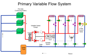
Today, many chilled water and hydronic heating systems are designed as primary variable. The pumps that serve the boilers or chillers also provide water flow out to the coils. Obviously in this type of system, if the terminal units close, the flow through the heat or cool source also stops.
The design engineer must prevent the pumps from running at no flow unless the pump was designed to operate that way. Very few pumps can operate at dead head for very long. The exception is some of the ECM smart pumps such as the B&G eco-circ®-XL.
Bad things happen around pumps at very low flow rates. The pump may build up heat. The pump may have premature seal or bearing failure. The pump impeller may be damaged. At best, the pump will have a short life. At worst, the pump may explode or leak hot fluid and hurt someone. The engineer’s design of the system should prevent operation below the minimum pump flow rate.
What is the Minimum Flow Rate of a Hydronic Pump?
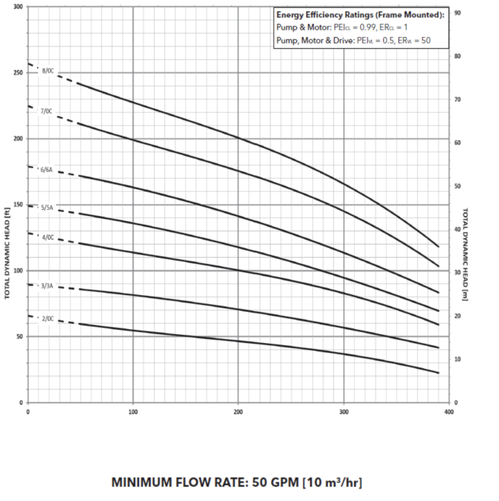
The manufacturer’s curve may show a minimum flow rate for a pump. The flow rate shown is normally for the pump operating at the full speed identified on the curve. Here are two examples:
This is a Xylem eSV multistage pump. These pumps are lower flow, higher head pumps. We selected this pump for 300 GPM which is close to the best efficiency point. This design point is 80% of end of curve which is a nice selection. The minimum flow is 50 GPM at the design RPM of 3500.
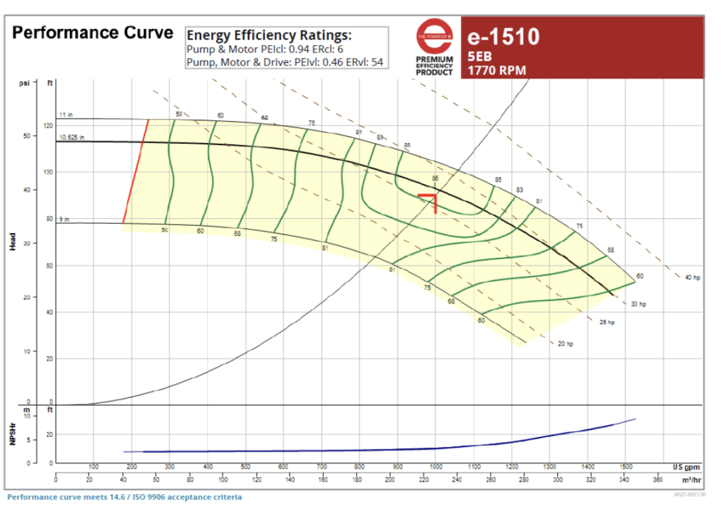
Here is another example. Let’s select a B&G e1510 end suction base mounted pump.
Once again, the minimum flow rate is shown by the red line. The flow is also listed in the submittal at 230 GPM for this constant speed curve at 1770 RPM.
So, if this was a constant speed pump, the manufacturer says to operate no less than 230 GPM at 1770 RPM. You might be thinking, “But Norm, most pumps I use in hydronic systems are variable speed. They save money and meet the ASHRAE 90.1 energy standards. What is the minimum flow at minimum speed?”
Determining Minimum Flow Requirement at the Minimum Operating Speed
The design of these hydronic systems with 2-way control valves should assure us of the minimum flow while operating at full speed. As the load drops, the 2-way valves start to close. The control system will react and lower the speed of the pump. Our real minimum condition occurs when the pump is at minimum speed. At that point, all or most of the control valves are closed. So, what is the minimum speed?
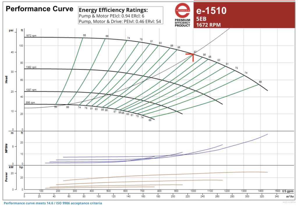
Here is that e1510-5EB with the same capacities of 1000 GPM at 90 feet at design. Now we select a control head. If you are not sure what control head is and you want a great resource, go to our collection of Monday Morning Minutes, and click on Pumps: Variable Speed.
For this example, we will assume a 25-foot control head.
We see that the minimum speed at the control head of 25 feet is about 700 RPM. Now we have all the information we need to determine the minimum flow at the minimum speed.
We know that speed varies proportionally with flow. This is the first pump affinity law. The minimum flow rate is 230 GPM at 1770 RPM. What is the minimum flow rate at 700 RPM? This is pretty simple math.
So, now you can calculate the minimum flow at minimum speed in a primary variable hydronic system. Next week we will explore best practices in order to achieve this minimum flow.


