Printer Friendly (PDF)
 The HVAC engineer designing a hydronic system understands the need to protect the circulating pumps from a dead head or no flow condition. This week, the R. L. Deppmann Monday Morning Minutes offers a few suggestions to accomplish this minimum flow rate in heating and cooling systems.
Two Ways to Meet the Minimum Flow Requirements in the Primary Secondary System
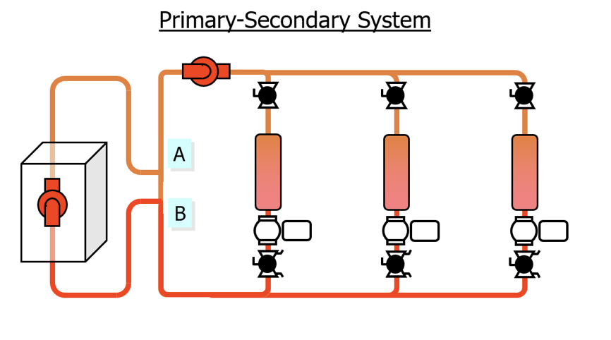
A traditional primary-secondary hydronic heating and cooling system is shown in the sketch above. The system normally has common secondary pumps which serve the terminal units. There is normally a primary pump for each boiler or chiller.
Since the primary pumps are on or off as needed, we turn to the secondary pumps which have two-way control valves. If all control valves close, the pump will be dead headed. This condition can create a problem. The designer should make sure the pump operates at the minimum flow required or greater. The minimum flow is determined as described in part 1 of this series.
There are many ways to meet this minimum flow rate. Let’s look at two options out in the system. The end of loop three-way valve and the end of loop balance valve.
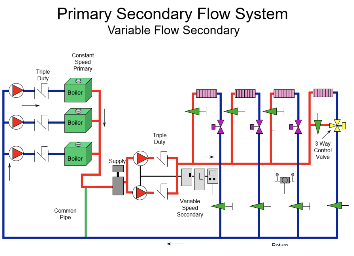
This simple representation above shows a secondary loop with two-way valves, but the last loop has a three-way valve. We would take, preferably, a small three-way valve at the end of each loop in various directions. The total flow of these three-way valves would add up to the minimum flow rate of the pump at the expected lowest speed.
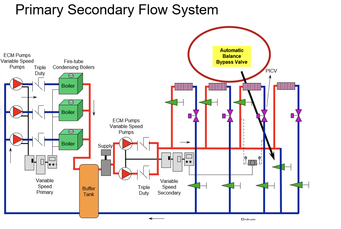
Here is a second option. In the system below, there are all two-way valves in the system but there is a bypass with a balance valve at the end of the loop or at the end of each loop. It is preferable that these valves be a Griswold or Bell & Gossett automatic balance valve set at the flow rates required to meet the minimum flow. This solution is simple but does cause water to flow in bypass constantly. This total flow would have to be added to the required system flow rate. A manual valve such as a B&G circuit setter could be used but the flow rate would increase as the pump head increases. This would waste more flow rate in bypass.
Both solutions have another advantage. The water flowing through each loop with the three-way or bypass balance valve will always be at the design supply temperature. This will help the temperature controls be more responsive to calls for heat or cooling.
The Issue with Minimum Flow Requirements and Variable Primary Systems
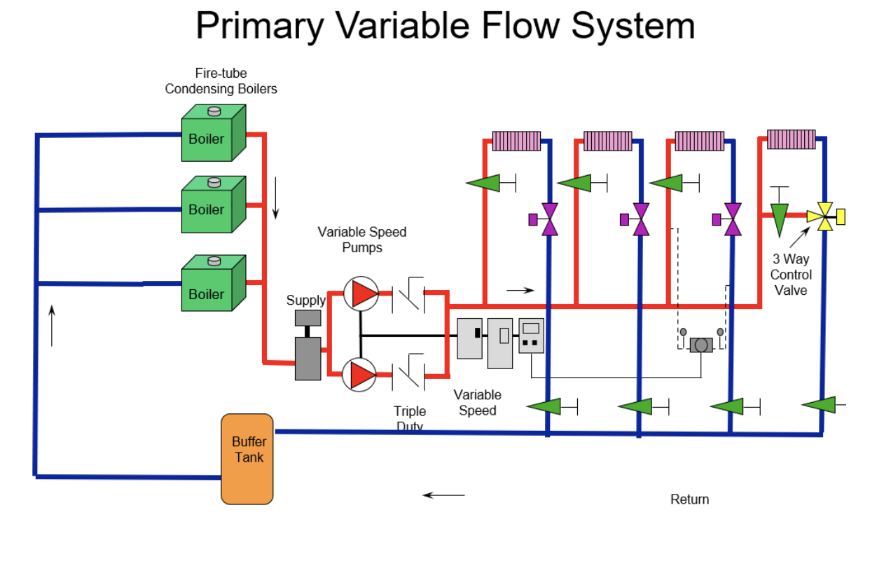
Today, there are more primary variable systems being designed than ever before. If the heat or cool source will accept variable flow rates, this system may reduce the number of pumps. In years past, these systems may have resulted in a flow rate through the on boilers as well as the off boilers. Condensing fire tube boilers are more efficient at low fire. The goal is to have as many boilers as possible operating at lower firing rates. If there are no control valves on the boilers, the three-way valve or bypass balance valve design mentioned above worked great.
Things have changed, ASHRAE 90.1 energy standards do not want flow through a boiler or chiller that is off. A pump or two-way valve is required to stop the flow through the sources that are off.
Now we may or may not have a problem with our traditional minimum flow solutions. We will address that subject in the next R. L. Deppmann Monday Morning Minutes.
Part 1: Minimum Flow in Variable Speed Pumps for Building Hydronic HVAC Systems