There are many advantages to operating two identical pumps at the same time. This method of pumping is called either parallel or series pumping. Today we look at the method of parallel pumping.
What is Parallel Pumping?
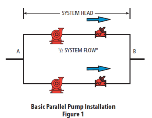
Parallel pumping is a design method that incorporates two or more operating pumps piped together and operated simultaneously to increase the total flow rate. Look at the sketch from the Xylem Bell & Gossett TEH-1109A Parallel and Series Pump Application technical manual. If each pump is flowing 50% of the design system flow, the total for the system will be 100% but the pumps will be smaller. Parallel pumping may use two operating pumps or three or more. The pumps are normally variable speed but may also be used in constant speed applications.
Parallel pumping is a method of selection and control of constant or variable speed pumps that mirrors the variable load we see in building comfort systems. We operate a single pump for most of the duty and when more flow is needed, we stage on the next pump.
Today, many systems have one pump designed for 100% of the flow and one pump sitting there as 100% standby. In parallel pumping, the design flow rate is divided between two or more operating pumps. If there are two operating pumps, the load is split 50%-50%. If there are three operating pumps, the load is split 33%-33%-33% and so on. While all the pumps are selected at this reduced percent of the design flow rate, the pump head for all pumps remains at 100% of the design head.
Developing Parallel Pump Curves
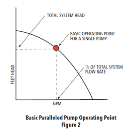
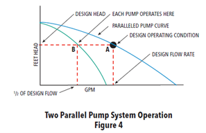
What does a parallel pump curve look like? When two pumps are operating in parallel, each pump does not change. The parallel pump curve is a mathematical representation of the sum of the published curves of the operating pumps. It is normally recommended that the pumps in parallel are identical. We will use the curves from the Bell & Gossett TEH-1109A Parallel and Series Pump Application.
We will show two pumps in parallel. Each pump is selected at 50% of the design flow rate at the total system head. This representation will show a single constant speed curve. This will keep the curves from getting too busy during the explanation.
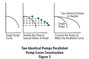 Each pump operates at the same flow rate and pump head.
- For every pump head point, we move across to the pump curve and read the flow rate.
- Since each pump is doing the same flow rate, we simply double that number. Now add a point at twice the flow at the head.
- Do this for many pump heads, and you will create a parallel curve representation.
Each pump operates on its curve but the sum of the two pumps is shown on the parallel curve.
Today, the Bell & Gossett ESP Systemwize program will do all this math and drawing for you. We will follow with an example next week.
Creating the Parallel Pump Curve in ESP Systemwize
Let’s look at the operation of variable speed parallel pumps in the closed hydronic system. We will use a big system as an example to explain the operation. Assume we have a large, chilled water system with a capacity of 3000 GPM at 150 feet. Also assume the control head is 40 feet. We will make this a secondary chilled water system so we do not complicate the example with minimum chiller flow rates, but it will work fine in a primary variable system as well.
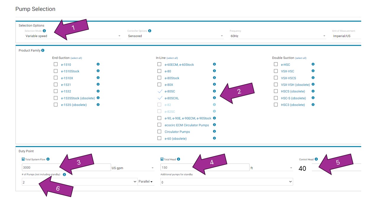
Start with the ESP Systemwize program. Here is what the input looks like:
- Input variable speed.
- Select pump type. We selected a vertical floor mounted inline this time.
- Enter the total system GPM.
- Enter the total system pump head.
- Enter the control head.
- Here is the magic: Change the parallel pumps to (2).
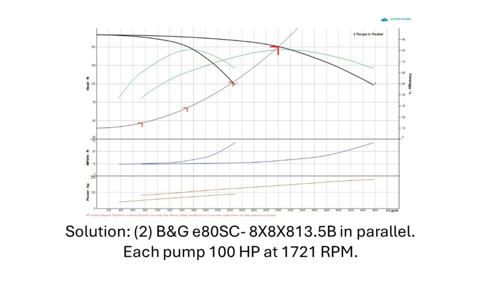
Press “get results,” and now we will have a parallel selection with a parallel curve:
Staged Operation of Parallel Pumps
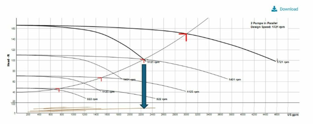
The operation of these staged pumps is best accomplished by the pump controller that B&G can provide. There will be times when two pumps are operating. Most of the time there will be a single pump operating. Here is the variable speed version of the parallel pump curve.
This curve looks busy, but the explanation is simple. A single pump will operate from the lowest pump speed of about 900 RPM to the “staging point” of 1721 RPM. This point is about 2250 GPM or 75% of the design flow rate. At that point, any additional flow required could not be accomplished by a single pump. The second pump would stage on and now both pumps would be operating at 1400 RPM and speed up together until the design flow rate is accomplished.
The staging point can be tricky. It is best handled by the pump manufacturer’s controls. We do not want to operate off the end of the single pump curve.
Why should an engineer look at parallel pumps? What advantages do they give the engineer? What should the engineer look out for to avoid trouble? All this will be answered next week in the R. L. Deppmann Monday Morning Minutes.

