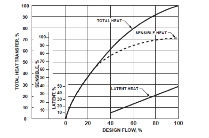
 The flow tolerance of a hydronic system is a critical component in the commissioning of an HVAC hydronic system. Should the balance report match the scheduled flow rates exactly? How close to the scheduled flow rates should it be? This is the first of five R. L. Deppmann Monday Morning Minutes looking at balance valves and variable speed pumping in HVAC hydronic systems.
Just to manage expectations – this week I will blog about flow tolerance. Next week’s article will show why we balance hydronic systems and the issues caused by not properly balancing a system. Then I will do a basic blog on balance valve types used in the HVAC industry and where to place them (you might pick up a point or two for your designs). Finally, we will resume with variable speed pump control and matching the system, control type, and balance type.
What is Hydronic Balance and Flow Tolerance?
A balanced hydronic system is one in which each zone and each terminal unit in the zone has the proper flow to satisfy the heating and cooling loads determined by the engineer. Notice, I did not say to get the exact flow rate scheduled for the terminal unit. The design, installation, and commissioning of a heating or cooling system is not a science class at university. The team is not attempting to make the numbers match the design in every way. The team is attempting to get the flow rates close enough to provide comfort for the client who is paying the team. That is where the term flow tolerance is important.
Hydronic flow tolerance is the percentage of the scheduled flow rate that the construction team needs to achieve in order to achieve the comfort of the building occupants. This is not the sole responsibility of the balancing contractor.
- The responsibility of the balancing contractor is to accurately adjust and read out the pumps and valves within the specified flow tolerance.
- The responsibility of the mechanical contractor is to purchase the specified valves and install them per the manufacturer’s installation instructions (IOM) and with the readout ports accessible to the balance contractor.
- The responsibility of the supplier is to determine the correct size, orifice, and pressure range for the product supplied.
- The responsibility of the engineer is to design the piping system and pumping arrangement to provide self-balancing where economically feasible. The engineer also determines the type and location of balance devices.
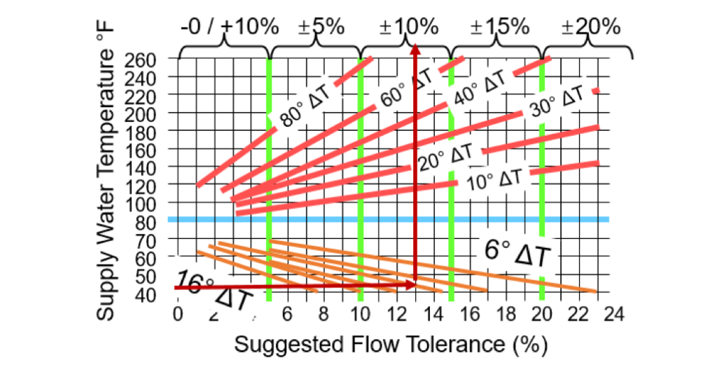
The American Society of Heating, Refrigeration, and Air-conditioning Engineers (ASHRAE) offers guidance on the subject of flow tolerance specification. Figure 34 of chapter 13 of the ASHRAE 2016 HVAC Systems and Equipment Handbook offers a chart represented here.
Here is an example of how to use the chart. If the supply chilled water is 44 degrees with a 10°F ∆T, enter the chart at the left and move over to the 10°F ∆T line. Then move up from there to read the flow tolerance specification suggested. This example specification should be 10%. Try this one. 180°F supply for the heating system and 40°F ∆T. For more on flow tolerance visit our Monday Morning Minute from July 2016.
So with today’s higher ∆T designs and lower supply temperatures, it appears the 10% flow tolerance is a great point to include in your specification.
Specification Review Points
Does your testing and balance specification include the flow tolerance? Does the hydronic, and for a talking point, the plumbing balance valve execution specification include this phrase?
“Contractor is responsible for the proper installation of balance and flow measurement devices including locating the readout ports for accessibility and proving the required pipe diameters.”
Next week the R. L. Deppmann Monday Morning Minutes continues the topic of balance and flow measurement examining why using the control valve to balance may not be the best choice.
Discover more on this Series: Balancing HVAC Hydronic Systems:
Balancing HVAC Hydronic Systems: Control Valves vs. Balance Valves (Part 2)
Balancing HVAC Hydronic Systems: Flow Measurement Valves (Part 3)
Balancing HVAC Hydronic Systems: Automatic Flow Limiting (Part 4)
Balancing HVAC Hydronic Systems: Pressure Independent Control Valve (Part 5)


