Printer Friendly (PDF)
 Giving up the 100% standby pump is often the major concern when using parallel pumping strategies for hydronic heating and cooling systems. This strategy can offer more comfort than many engineers realize. This blog will walk you through the methods of providing standby capacity in those rare times when one of the pumps is offline in parallel pumping.
How Much Can One Pump Do?
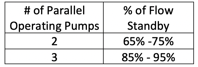
In the last blog, “Controlling Parallel Variable Speed Pumps”, I showed the staging points for different parallel pump operations. In a two-pump system, a single pump can provide much more than 50% of the flow. In a three-pump system, two pumps can provide more than 66.6% of the flow. The examples I used showed 70% for a two-pump and 90% for the three-pump system with one pump down.
The staging point or operation with one less pump for your system will depend on the pump curve selected and the system control head. The farther right of best efficiency point (BEP) you select the pump, the less standby capacity. The higher the control head you choose, the less standby capacity. My rule of thumb for approximating standby capacity is:
Do you need 100% Standby Capacity in a Heating or Cooling System?
I would start by asking, how often are you at design condition in a heating or cooling system? Do you have a 100% standby machine to create the heating or cooling? If your boilers or chillers are at N+1 capacity, you may have determined there is a need. Maybe it is a process system where shutdown is not a possibility. Maybe it is an emergency facility. Maybe the owner is just willing to pay the extra costs.
In those systems where 100% standby is needed, you should either stick with the 100%-100% system or if parallel pumping is going to save a great deal of cost, you could go to an N+1 strategy with pumps. Use 50%-50%-50% in smaller systems or 33%-33%-33%-33% in larger systems.
How critical is a standby pump?
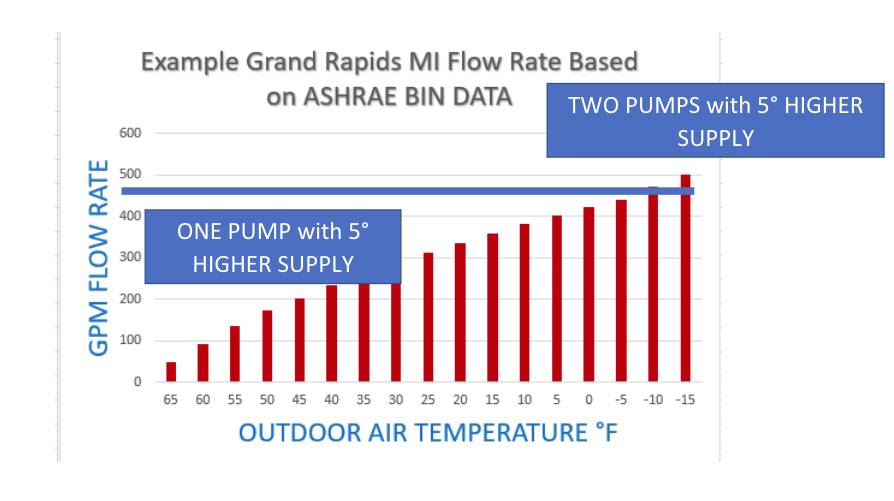
I started this series with a look at a heating system in Grand Rapids, Michigan. Let’s look at the ASHRAE heating BIN data and what the flow rate looks like in that example.
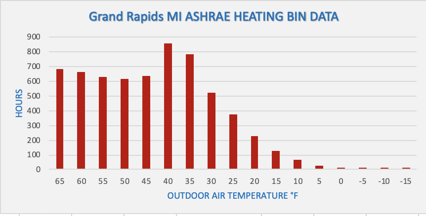
We can see that the weather outside is only cold enough to require 100% capacity a small fraction of the actual operating hours. How much flow rate do you need for how many hours?
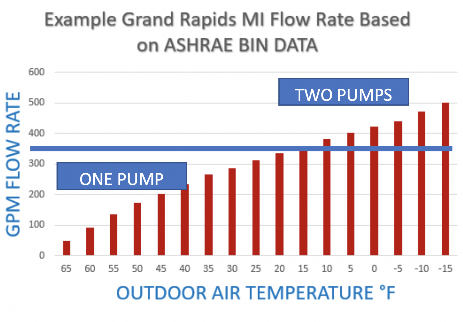
We can see that two pumps will be required when the outdoor weather is below 15°F. In Grand Rapids, this may occur only 3.6% of the heating season. What are the odds? Let’s tip the odds even more in our favor by looking at ways to game the system in an emergency.
Getting More from Your System – Three Ideas
Idea 1: Raise the speed of the pump.
In an earlier blog, “Over speeding of Variable Speed Pumps”, I offered a way to get more out of your existing pumps. By raising the speed of the pump above the nameplate speed of the motor, you will get more capacity.
Let’s look at the variable speed curves in our Grand rapids example.
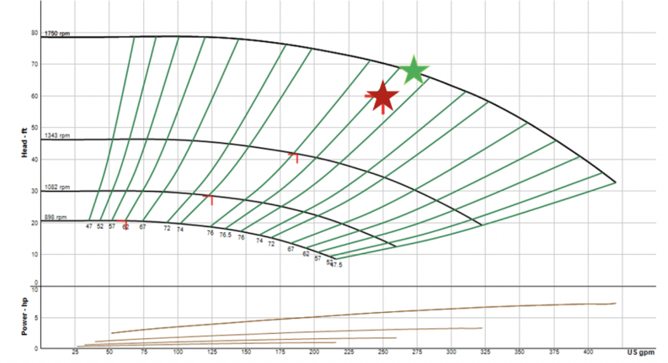 Red star is the design point speed. Green star is at over-speeding.
The extra flow rate will get us to 75% of design flow in a single pump operation. We now can satisfy the load at 10°F outside temperature or higher.
In an emergency, look at raising the speed of the pump and lock it in manual mode at that speed.
Idea 2: Raise the outlet temperature of the boiler by 5°F.
In our example, we assumed a design condition of 180°F supply and a 140°F return temperature. This 160°F average temperature will provide the required heat transfer at the terminal units. The terminal unit heat transfer “U-value” and LMTD (log mean temperature difference) used this design average temperature. If I raise the design temperature, I can get more heat transfer in most terminal units.
The small increase in temperature shown above will give you about the same BTUH output with 5% less flow rate. The effect of these two “tweaks” in an emergency, results in a single pump operation providing heat close to design.
Idea 3: Drop the space temperature setting in non-critical areas.
Does every space need 70°F. Dropping noncritical spaces by a couple degrees may be another strategy to supply 100% of the needs in critical areas.
Most parallel pumping systems are operated as if there was a standby pump. That is because the combination of safety factors and weather make the pumping system look as if they have a standby pump. Don’t be afraid of the loss of standby pump. Just understand how much standby you really have in parallel systems.
HVAC Hydronic Series:
Article 1: What is parallel pumping and why do it?
Article 2: Selecting parallel pumps and the curve
Article 3: Controlling parallel variable speed pumps
Article 4: Parallel pumping and standby capacity
Article 5: Parallel pumping and cost
Article 6: Parallel pumping specifications