The variable frequency drive can vary the speed of the centrifugal pump from zero to speeds over the nameplate of the motor. Of course, the horsepower and the pump manufacturer may limit the minimum and maximum speeds. The VFD can change the speed of the pump but something or someone must cause the speed to change and what speed to settle at. Today, the R. l. Deppmann Monday/ Morning Minutes looks at sensing methods in HVAC and Plumbing systems.
Types of Sensor Points in Systems
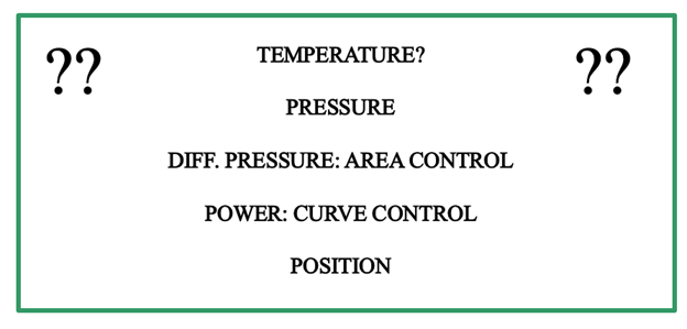
We will take time to review many types of pump speed control. The control signals we will review for hydronic heating and cooling systems are Manual, Temperature, Pressure, Differential Pressure, Horsepower Draw, and Valve Position. There are more options, but these are the most common in the industry today. We will comment on each type as we describe them. The choice of control remains with the engineer. Our goal is to offer information that will help the engineer in the decision.
Variable Speed Pump Control by/ Temperature
In most HVAC systems we are attempting to maintain a space temperature within a chosen range. It seems that adjusting the hydronic system pump speed to meet the temperature requirement would make logical sense. In fact, those of you with grey hair or no hair and even possibly retired long ago may remember that the first attempts at variable speed control used temperature.
Early systems with temperature control attempted to place a sensor on the return water header to control the pump speed. The idea was to maintain the delta T across the system and let the flow rate drop in direct proportion to the drop in BTUs required.
Look at the high school example system below. What if the temperature sensor was on the return header back to the pump. The problem is that the temperature sensed is a mixture of return water from all five zones. The pump speed, and therefore the flow rate, is an average mix of the zones. Some zones may get too much flow, while others will be short and have complaints.
There are systems where a single zone has temperature control. There are advantages and disadvantages, and this is a complicated subject. You may read a bit more about this at Constant Speed 2-Way Control vs. Variable Speed Pumps and Constant Speed 2-Way Control vs. Variable Speed Pumps.
For HVAC systems in general, Variable speed pump control by temperature sensing is not a normally used option.
Variable Speed Pump Control by/ Pressure
The next generation of variable speed pump control in HVAC systems was pressure. In closed HVAC hydronic systems, this is not a good option. The expansion tank or point of no pressure change is near the pump suction. It remains constant at any temperature but as the temperature changes in the hydronic system, so does the pressure at the expansion tank. That means that a pressure sensor out in the system reacts to both pressure drop in the supply and changes in temperature. This will result in no real control based on load.
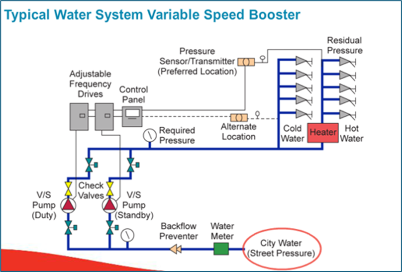
Plumbing pressure booster systems are a different animal. In a pressure booster system, we are increasing the water from the supply pressure to a greater pressure to meet the pressure demands at the hydraulically farthest fixture. The system maintains a constant temperature.
Look at the system above. The pressure sensor in this open plumbing system is shown at the top of the building near the farthest fixture. We are trying to maintain the required pressure at the flush valve. This location allows us to sense changes in suction pressure from the city as well as pressure drop in the piping system.
If the pressure booster sensor was located at the discharge of the pump, it would still work but it would lose energy savings due to variable friction loss. Obviously, the first cost is lower if the sensor is mounted on the pump skid. That energy savings vs. first cost calculation will be part of the engineer’s decision on where to locate the sensor.
Never use pressure only sensing in a closed hydronic system
Always use pressure sensing in open pressure booster plumbing systems.
Variable Speed Pump Control by/ Pressure Differential
Differential pressure (DP) is a tried-and-true method of closed hydronic system centrifugal variable speed pump control. We introduced this in a previous R. L. Deppmann Monday Morning Minutes: What is Control Head in Hydronic Variable Speed Pumping?
The pressure differential sensor transmitter will take advantage of reduced pressure drop in both the supply and the return as the flow rate drops. It is important to identify where the sensor should be installed and what the starting differential pressure should be. If you put it too close to the pump, there will be less energy savings. If you install it in the wrong place, you may have to increase the control head so the farthest zone has the proper DP. This will also reduce energy savings.
What happens to energy savings if we miss the location of the DP sensor? Let’s look at the example problem from the last blog. The blog indicated the correct location was at the points marked “A.” What if the sensor was at “B”? What if you did not show it and the contractor installed it in an easy location across the pump?
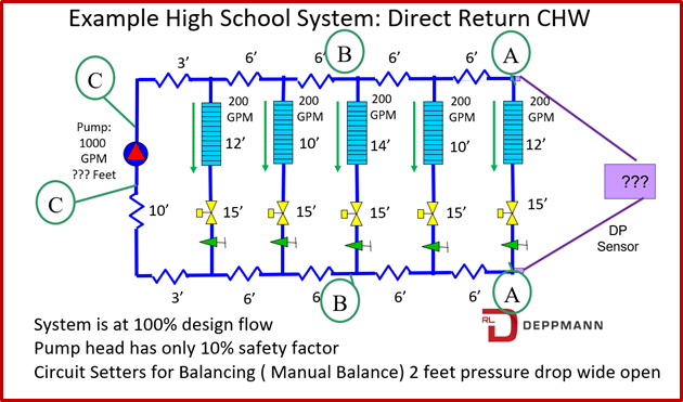
When you are looking at the pump curve, the area between the full speed curve and the control curve is a representation of the energy savings. What are the control heads at each of these locations?
Point “A” we know from the last MMM. The control head is 29 feet.
Point “B” will be the 29 feet plus the supply and return pressure drop after the sensor. The supply from point “B” to “A” is 12 feet. So is the return. The control head required would be 29+12+12 = 53 feet.
Point “C” is the worst case. It will be the 52 feet from point “B” plus another 15 feet on the supply and another 15 feet on the return piping plus the 10 feet in the mechanical room or 52 + 15 + 15 + 10 = 92 feet
What does a typical hydronic heating water system pump energy cost per year look like in the high school example? We will use the B&G Systemwize program. Obviously, the load profile and energy cost will change the numbers, but this gives you a relative comparison. Feel free to go to the program and the results will show the energy savings in dollars for your comparison.
B&G e1510-5GB at 40 HP.
1000 GPM at 105 feet.
180 days per year operating at 11¢ per KW.
| Control point A 29’ | $5,654.00 |
| Control point B 53’ | $5,836.00 |
| Control point C 92’ | $6,084.00 |
We can see there can be significant energy differences based on control head and sensor location. Next week we will look at two more sensing types to complete this blog.