Printer Friendly (PDF)
In the last R. L. Deppmann Monday Morning Minutes (MMM), What is Control Head in Hydronic Variable Speed Pumping?, we mentioned a quiz and asked three questions. Unfortunately, the sketch shown above was not shown so it would be impossible for you to answer. This MMM will ask the same questions and provide the answers. We will also include a variable pump selection. Next week we will continue with various variable speed control strategies.
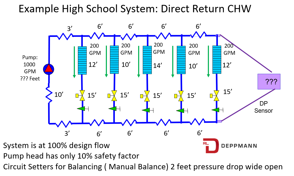
Question 1: What is the control head of the system shown above?
We introduced the concept of control head in the last MMM, What is Control Head in Hydronic Variable Speed Pumping?. We defined it as the pressure drop across the controlling zone or the one that determined the pump head. The pressure sensor is shown across the farthest zone in our example system. The design flow rate, in that zone, is 200 GPM. At 200 GPM the zone has pressure drops of 12 feet through the coil, 15 feet across the wide-open two-way control valve, and 2 feet across the wide-open B&G circuit setter.
So, the control head is simply 12+15+2 = 29 feet. If the system has water, the pressure setting would be 29/ 2.31 = 12.55 PSIG. We would not give such an exact answer to the control contractor. The plans could simply say set the control head at 13 PSIG which is close enough.
Question 2: What is the pump head with no safety factor?
OK, this is basic, but this MMM series is basic. We simply add all the pressure drops shown as we journey from the pump to the controlling zone which is the last zone in this example. Since there is no other equipment or valves in the simple sketch, you can assume the friction loss through service valves and fittings are included.
Starting at the pump discharge we see distribution losses:
Pump discharge to zone 1: 3’
Supply Zone 1 takeoff to zone 2: 6’
Supply Zone 2 takeoff to zone 3: 6’
Supply Zone 3 takeoff to zone 4: 6’
Supply Zone 4 takeoff to zone 5: 6’
Zone 5 pressure drop (calculated above as control head): 29’
Return from zone 5 to zone 4: 6’
Return from zone 4 to zone 3: 6’
Return from zone 3 to zone 2: 6’
Return from zone 2 to zone 1: 6’
Return from zone 1 to mechanical room: 3’
Mechanical room PD from zone 1 to pump suction: 10’
Total pump head: 93’
So, the pump head with no safety factor is 93 feet.
Question 3: What is the pump head including the 10% safety factor?
Now we simply add 10% to the pump head. 93 X 1.1 = 102.3 feet. People would smile if you had a decimal point on a pump head schedule. If you just graduated that may not be known to you. I remember placing answers on exams that were carried out to a couple decimal points.
In the real world, we would round that number up. An answer like 103 feet or even 105 feet would not be unusual and would be correct. What is rarely done in our industry is a rounding down. Let’s say the answer is 105 feet.
The pump would be selected for 1000 GPM, the total of all the flow rates, at 105 feet. There could be some diversity where one zone would be off when another was on but there was no mention of that so we will stick with adding all the flow rated up to 1000 GPM.
Question 4 (added): Select a B&G pump based on the information above.
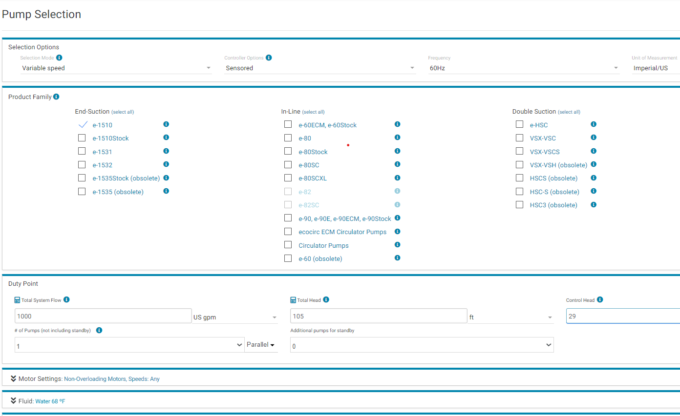
Let’s use the B&G Esp-Systemwize pump selection program. R. L. Deppmann is the B&G representative in Michigan and Northern Ohio so that should not surprise you. We will select an e-1510 base-mounted pump. We’ll show you the screens as we do it and briefly introduce one concept in pump selection.
Step 1: Enter the data.
We entered the flow and head and control head. We used the default of water as the fluid. We also used the default of a non-overloading motor as mentioned in What’s On a Pump Curve?.
Step 2: View results
These are just a few of the pumps offered by the program. We reduced the number of columns shown to make it easier on your eyes. We also sorted by first cost. The program defaults to sorting by efficiency and we will look at that, but cost is always an issue in construction.
We placed an “X” by the pump we would select. There will be more details about pump selection in a few weeks, but we will outline the reasons we selected this pump.
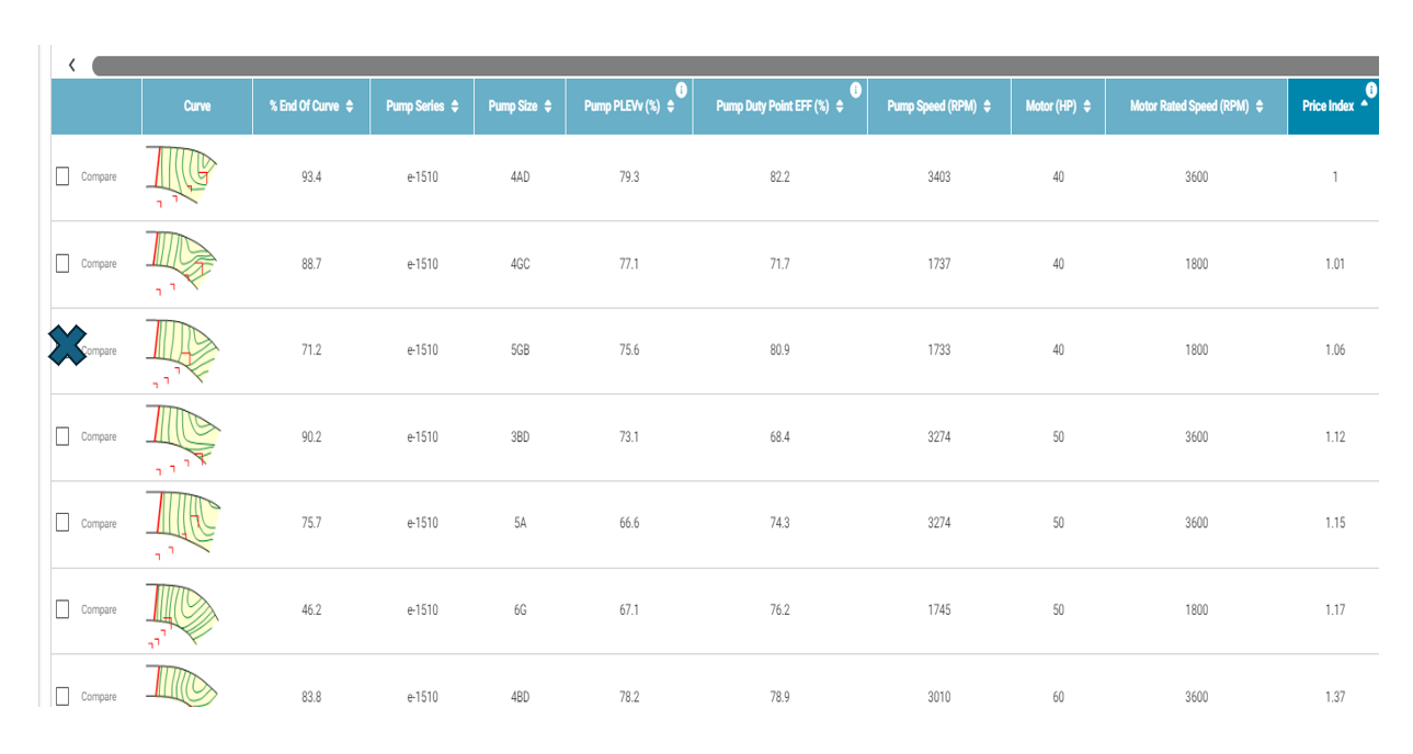
In the last column, you will see that we selected a pump which is 6% more expensive than the first one on the list. You will also notice the efficiency is slightly lower than the first selection. So why are we selecting this more expensive pump with a little less efficiency?
Look at the first column called “end of curve.” In general, it is recommended to stay away from the end of curve. These systems are not static and if you operate past the end of the curve, terrible things can happen to your pump which would not be covered under the manufacturer’s warranty.
Here is a past blog if you want to read ahead about pump selections and end of curve. Bell & Gossett Part Load Efficiency Value Part 4: End-of-Curve Selections.