Printer Friendly (PDF)
Control head is a term used in many different industries. What is the control head in our world of variable speed pumping hydronic and plumbing systems? Here at R.L. Deppmann we define “control head” as the minimum pump differential that the variable speed pump will ever produce while in operation. The minimum pump head exists even if the flow rate is zero or near zero. We will explain it further but first let’s look at an illustration.
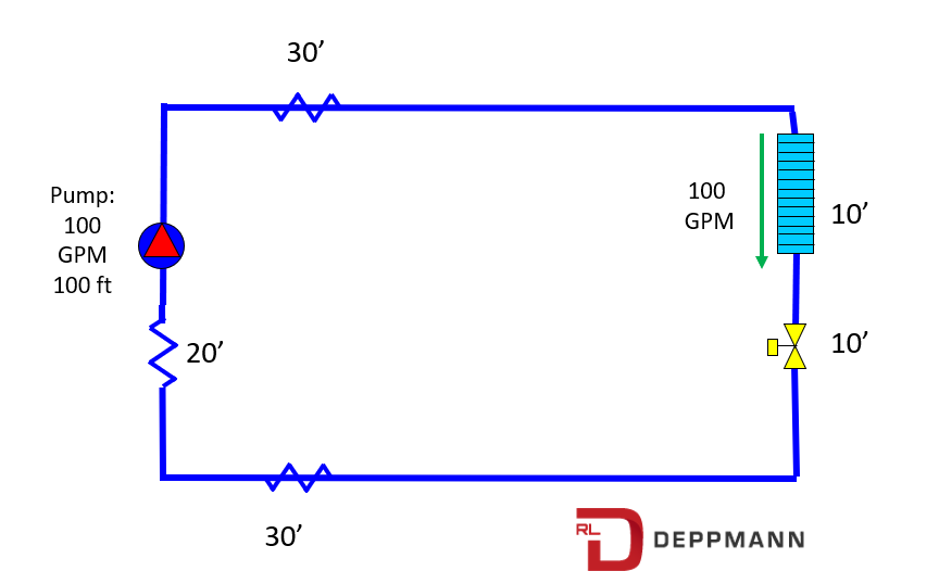
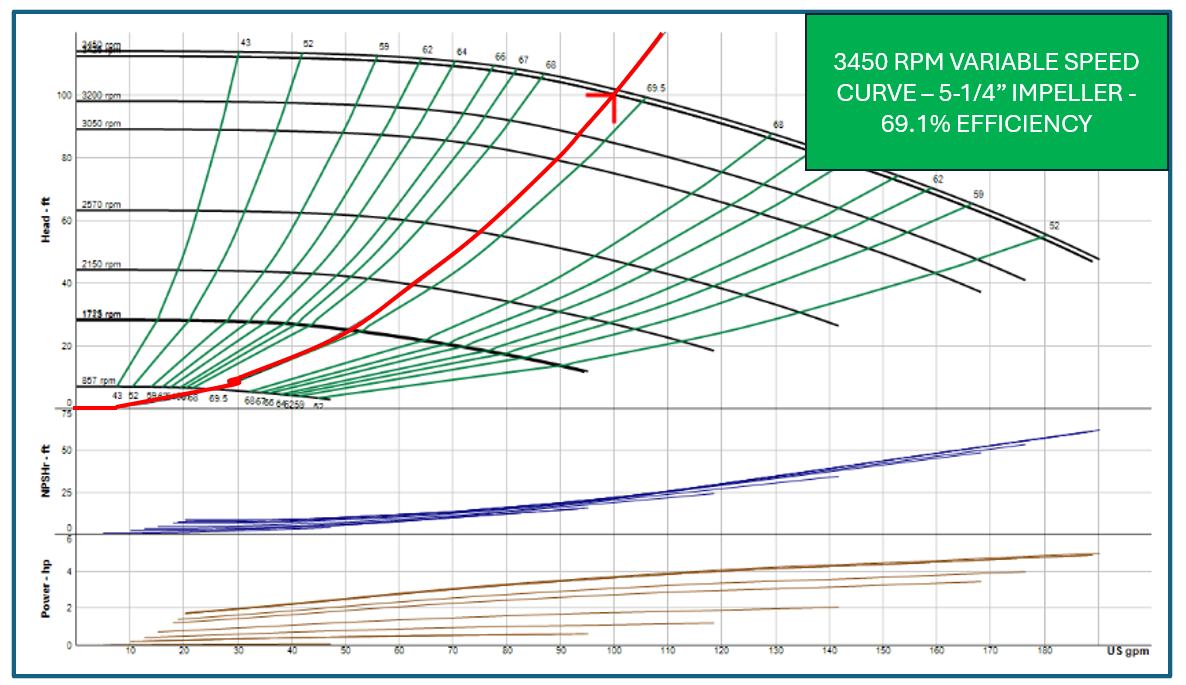
In our blog, Developing Variable Speed Pump Curves, we showed an example pump selection of 100 GPM at 100 feet of head. We also showed a theoretical “system curve” based on the second pump affinity law.
In most hydronic systems, a capacity of 100 GPM at 100 feet would be odd. We used it so the reader could think of it as 100% flow at 100% head.
Let’s assume the pump above is operating in a system with the control valves fully open. In a perfectly balanced system, the pump is operating at 100 GPM at 100 feet of head.
Now something changes and the flow rate required is only 50 GPM. In a constant speed system, the control valves would throttle and the pump would operate at 50 GPM at about 115 feet of head as shown in our Three-way & Two-way Control Valve Basics in Hydronic Systems blog.
In a variable speed system, we want the speed to drop and the pump head to drop and save energy. But what tells the speed to drop?
The pump will operate at the intersection of the pump curve and the system curve. So, for each speed, there is a point of operation. How does the pump know what speed to operate at? There are several acceptable methods used to tell the pump where to operate. We will look at this next week, but today we will look at a common method of pressure differential as we explain control head.
System Pressures in a Constant Speed Pumping Example
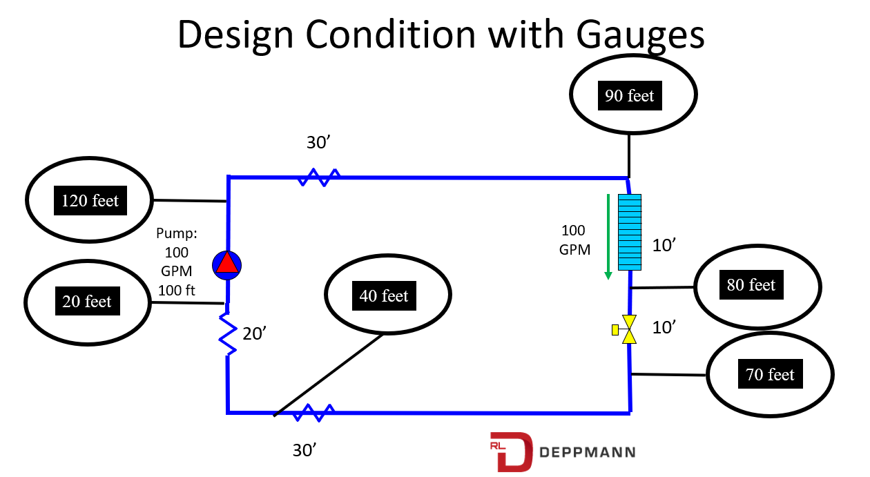
Look at the simple representation of that coil shown above. What happens when the two-way valve throttles to reduce the flow rate?
The space temperature control tells the two-way valve it needs less flow rate so the two-way valve throttles and tries to increase the pressure drop to move back on the full speed curve to 50 GPM.
The pressure drop in the distribution system reduces significantly as the flow rate drops. In a constant speed system, this is what the numbers would look like.
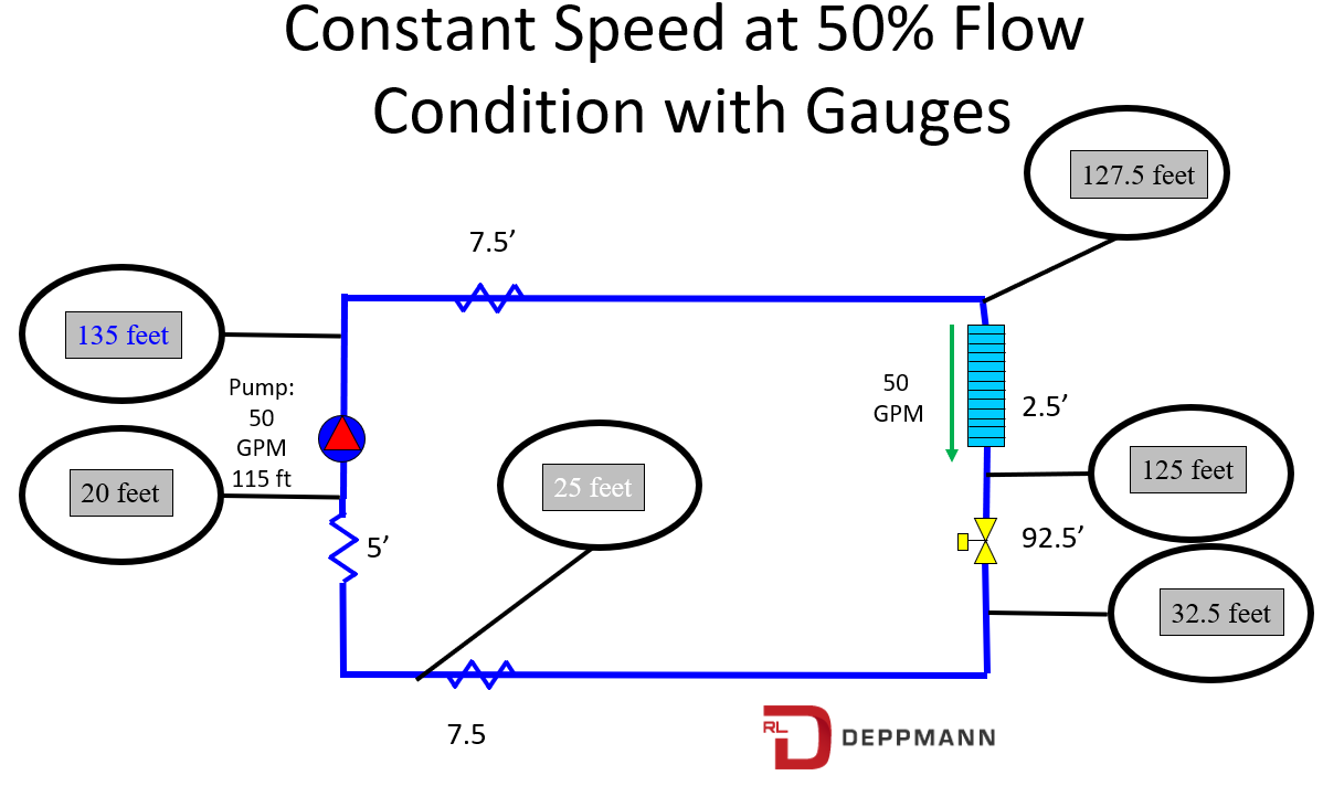
Since the pressure drop in the piping and components dropped, the two-way valve throttles significantly. This is the wasted energy that variable speed pumping system can save.
Pressure Differential Pump Speed Control Head
In a pressure differential controlled variable speed pumping system, the sensor is normally located at the farthest loop or the loop that caused the pump head in your calculations. The differential set point is the pressure drop of the coil, two-way valve, and balance valve in the controlling zone. In our example of a simple one zone system this would be 10 feet for the coil and 10 feet for the open control valve or 20 feet.
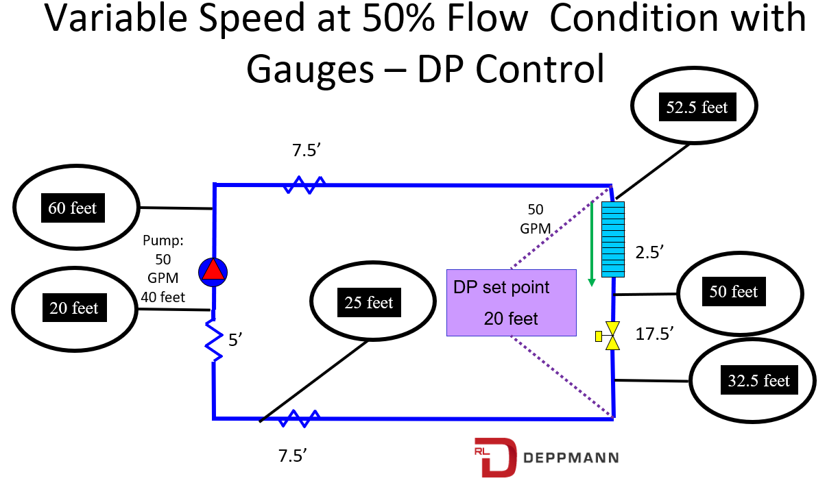
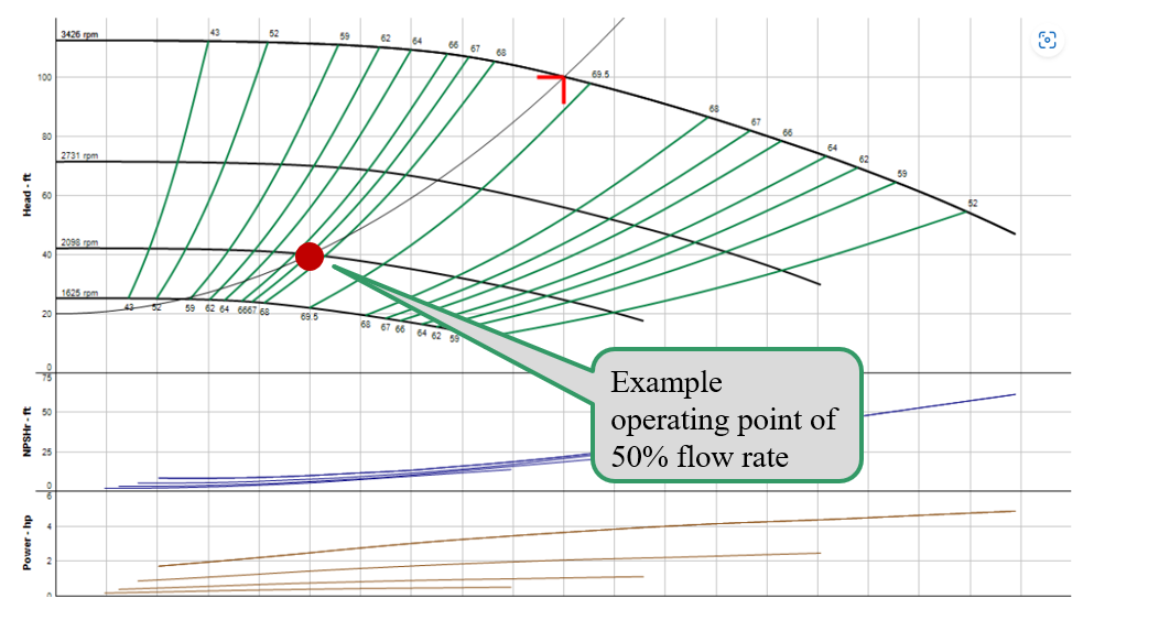
The control head, in this example, is 20 feet. The system curve does not start at 0 GPM at 0 feet. It starts at 0 GPM at 20 feet. Now, as the two-way valve starts to close in response to the space condition, the pressure differential across the controlling zone will try to rise but the speed of the pump will reduce instead. Here is what the pump curve looks like with the new system curve including the control head. We used the ESP Systemwize Bell & Gossett pump selection program.
The control head assures us that there will always be enough pump head at the controlling coil to meet the design GPM. Think about it. As the two-way valve starts to open from this 50% point what will happen? The flow will increase a little, the piping pressure drop will increase, the differential at the controlling coil will decrease, the pump will speed up to maintain that differential.
Homework Quiz for You to Try
Look at this representation of a high school chilled water system with five zones.
Questions:
- What is the control head?
- What is the pump head with no safety factor?
- What is the pump head with the stated safety factor?
Answer these for yourself and we will publish the answers next week.
There are times when we may want more than one sensor. There are times when the location of the sensor may change. These are topics for a later R. L. Deppmann Monday Morning Minutes. Next week we will look at other means of controlling the variable speed of the pump.