Printer Friendly (PDF)
An engineer asked a question about using variable speed pumps for air temperature control in lieu of a two-way control valve. The question clearly makes you stop and think. I have a heating coil with a circulating pump. I have primary-secondary piping. Variable speed pumping technology is changing every year. Is this an option I should explore?
Traditional Primary-Secondary-Tertiary Coil Pumps
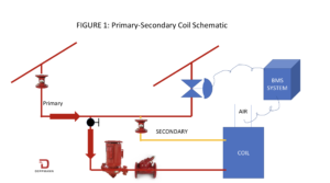
Look at the primary-secondary heating system shown above. This would normally be the tertiary loop from a primary variable system. The pump circulates the coil and pulls water from the main heating or cooling loop to the coil. As the 2-way valve throttles, the constant flow tertiary coil pump will mix the return water with the lower flow from the secondary.
This results in a mixing in the common pipe and a reduced temperature entering the heating coil. As the coil air temperature sensor gets closer to set point, the supply water temperature drops. As the coil air temperature drops and gets farther from set point, the supply water temperature rises until it is at the intended supply temperature.
Note that the flow rate is constant through the coil and the inlet temperature to the coil is the variable.
If you are not clear on this primary-secondary piping operation, here is a short video.
Variable Speed Tertiary Coil Pump Control
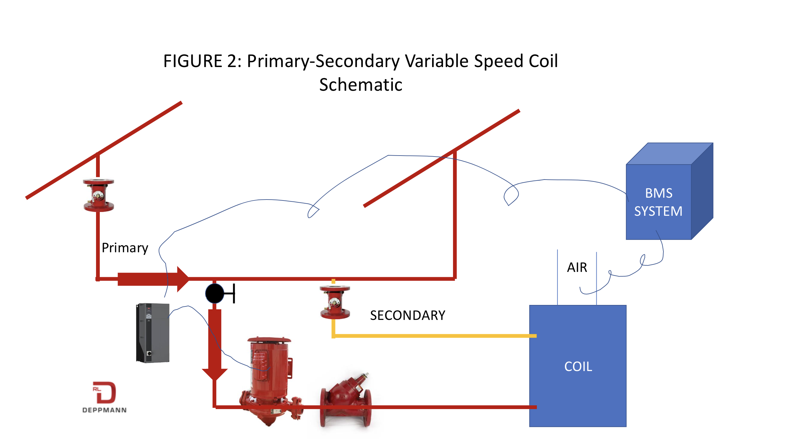
If we vary the speed of the coil pump, we will change the velocity in the coil. Look at the two representations above. Figure 2 shows a primary-secondary loop with the 2-way valve missing. The building management system (BMS) sends a signal to the drive or ECM pump to change the speed as required to maintain the air temperature. The primary loop may be constant flow or variable flow. As the flow drops through the coil, the coil flow rate may be less than the flow rate from the primary. There is water bypassing the coil system from the mains. This bypass flow will raise the return temperature to the boiler plant. The flow rate at the coil, and thus, the velocity, through the coil changes.
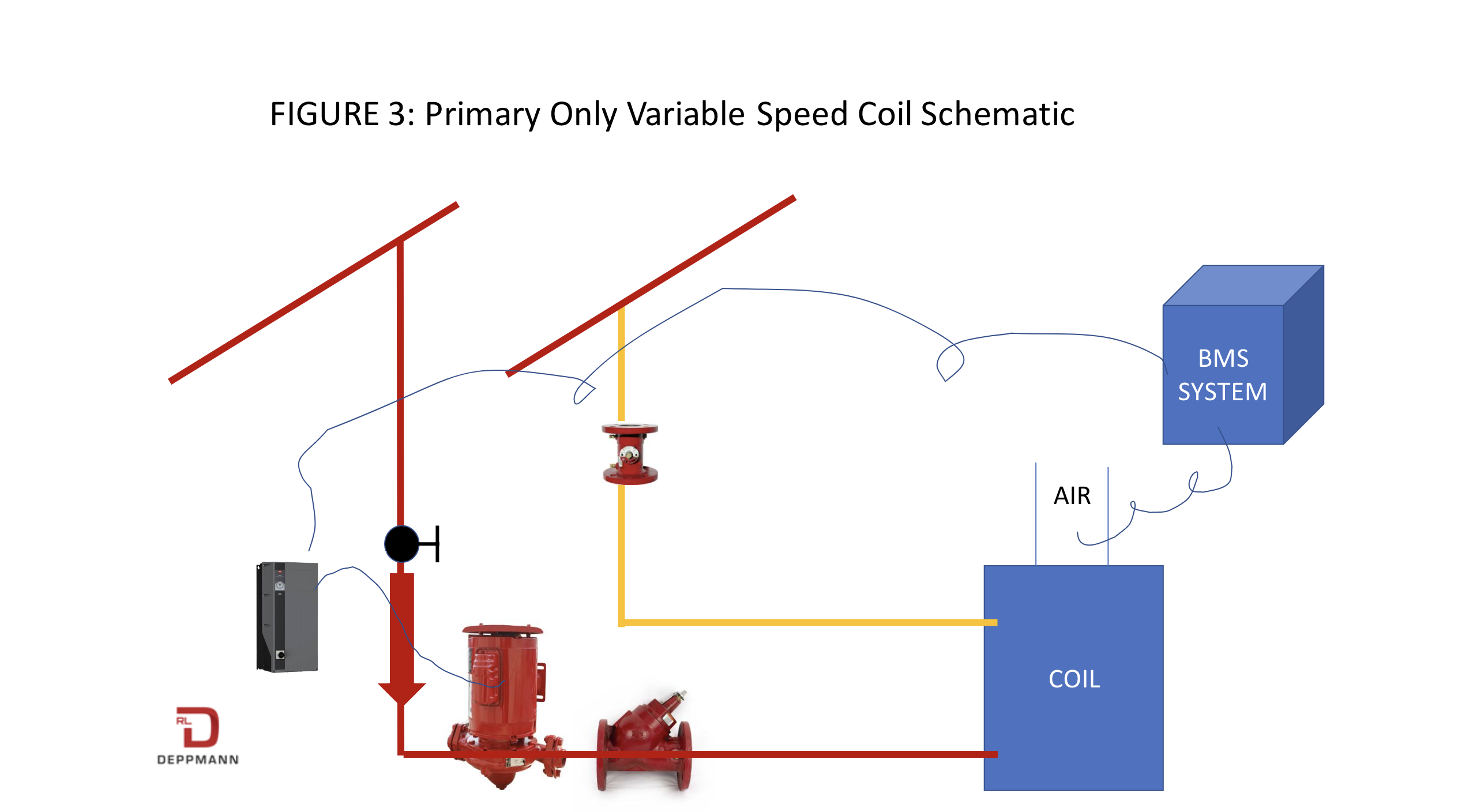
Figure 3 eliminates the common pipe, and we no longer have a primary-secondary piping arrangement at the coil. As the flow rate through the coil drops, the flow rate in the mains drop. The coil is not decoupled from the main system.
What is Happening at the Coil?

What is happening in the traditional primary-secondary piping with a 2-way valve? Remember, the flow rate remains constant, and the temperature supplied to the coil changes. The coil BTU per Hour output changes because the log mean temperature difference (LMTD) drops. Much of the “U” value involves velocity which remains constant. We have little heat transfer concern about the Reynolds number becoming transient or laminar. The “U” value of the coil changes a small amount due to temperature, but we can call it constant.
In figures two and three, the temperature from the main system remains the constant temperature to the coil. The flow rate, and thus the velocity, through the coil varies. In the BTUH formula, the LMTD remains constant and the “U” value changes.
As the flow rate through the coil becomes low, there is a concern about laminar flow. At transitional and laminar flows, the “U” value in the coil will drop suddenly as will the BTUH output of the coil.
What are the advantages and disadvantages of variable speed coil pumps? Visit our next R. L. Deppmann Monday Morning Minutes to find out.