Last week, in part one of this series, we looked at temperature, pressure, and differential pressure sensors to control the speed of a HVAC or plumbing centrifugal pump. Today, R. L. Deppmann Monday Morning Minutes offers you part two of this topic. Today we look at pump drive controllers that use the theoretical control curve to change the speed. We also look at the two-way valve position to determine the speed of the pump.
Theoretical Control Curves and Diversity
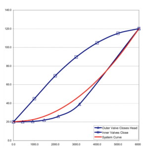
So far, we have used the theoretical control curve when discussing sensors and control signals to the variable frequency drives. We introduced you to the closed system curve in the Closed System Curves in HVAC Hydronic Systems. We adjusted the system curve to create a control curve in What is Control Head in Hydronic Variable Speed Pumping?. These curves assume that all the coils and terminal units in the hydronic system are modulating to the same percent of design flow rate.
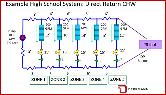
Look at the simple example system above. Our control curve assumes that if zone 5 requires, for example, 35% of the design flow, that zone 1 also requires 35% of the design flow rate. We know that between solar loads, people load, and daily activities that the perfect theoretical load curve will not match the actual load.
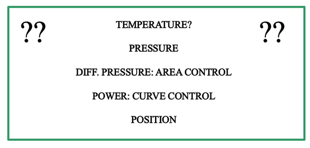
We will refer to the term curve control to indicate control solutions that must follow a preset curve such as the system curve. Systems that can react to diversity are called area control. Visit Variable Speed Pump Control: More Detailed Curve & Area Control for a more detailed explanation.
Sensorless Variable Speed Pump Control (Curve Control)
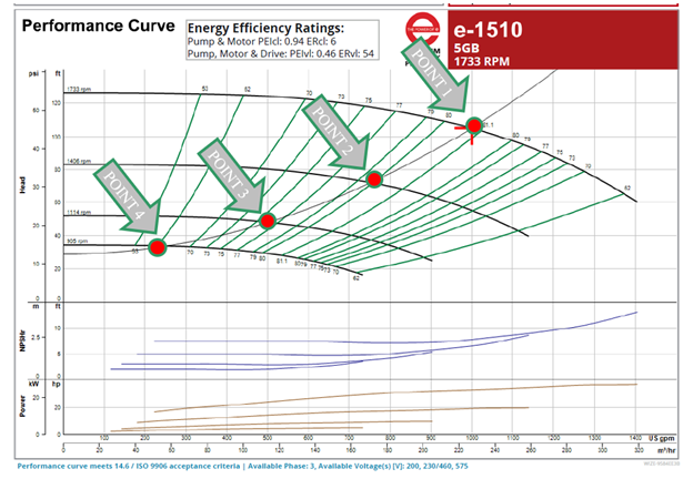
One control method is sensorless control. It does not have sensors out in the system. Instead, the sensor is motor amp draw sensing electronics and the pump speed included in the local pump controller or variable speed drive (VFD). Let’s look at the example system pump curve shown above. The curve was selected using the Bell & Gossett Systemwize program.
For each of the points shown, there is horsepower and speed. Keep in mind that there are an almost infinite number of speed curves, but we are just showing four to keep the explanation as simple as we can make it. We will calculate the horsepower at each of the points shown.
Point 1: (1000 X 105) / (0.81 X 3960) = 32.7 BHP and 1733 RPM
Point 2: (775 x 70) / (0.80 x 3960) = 17.1 BHP and 1406 RPM
Point 3: (500 x 50) / (0.76 x 3960) = 8.3 BHP and 1114 RPM
Point 4: (225 x 35) / (0.62 x 3960) = 3.2 BHP and 905 RPM
The program has the control curve formula in the computer. For every point on the control curve there is a corresponding amp draw just as we calculate the horsepower above. The program says that the pump MUST follow the control curve. For every point on the control curve there is a corresponding speed and an expected corresponding amp draw. The electronics simply measure the amp draw and looks at the speed. It adjusts the speed until the amp draw matches what is expected. It is a bit more dynamic than that but let’s talk it through.
For example, the pump is operating at point one and 1000 GPM. Now the two-way valves start to close, and the pump tried to back up on it’s curve to 750 GPM as discussed in Three-way & Two-way Control Valve Basics in Hydronic Systems. If it were constant speed it would move to 118 feet of head. But that amp draw does not match the table expected amp draw. The controls start to drop the speed and recheck. It does this quickly and continuously until the speed gets to 1406 RPM where the corresponding amp draw and speed are correct.
Keep in mind that it assumes all the valves throttled at the same time. More about this next week. What this system does do for you is it reduces the field labor of installing and wiring remote sensors, and that can save first cost dollars.
Sensorless variable speed control is a great cost-effective method to control the speed of a pump in a closed hydronic system with lesser amounts of diversity. Sensorless should not be used for plumbing pressure boosters or recirculation systems.
Demand Reset (Valve Position) Variable Speed Pump Control (Area Control)
The goal of variable speed pumping is to save the wasted energy across throttled two-way control valves. Of course, to satisfy the space temperature requirements, two-way valves are used.
Our last control method to review in this blog is the valve position control method. This method will be the most effective for energy savings but will, in most cases, be the most expensive from the initial cost.
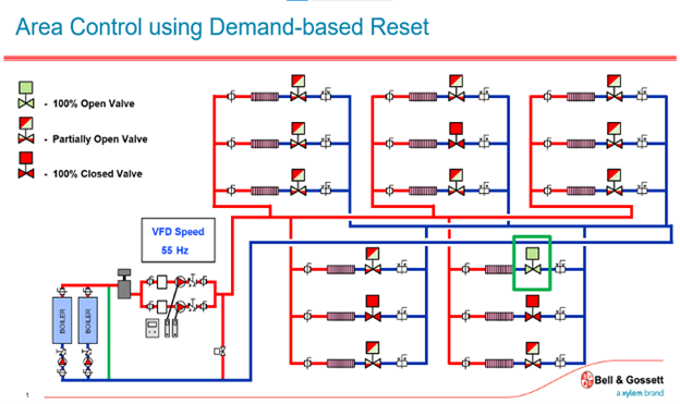
How does this work? This system requires the building management system to understand the position of all the control valves in the system. This is not just “is the valve open or closed.” It means is the valve at 90%, 50%, 25%, or some other percent open or closed.
Each control supplier may have a different setup, but it operates like these steps. Check each valve position, reduce the digital signal to the drive, and change the pump speed until one valve is 90% to 95% open. If the valves throttle more, reduce the signal and pump speed until the 90% to 95% target is met. If the valve goes to 100% open, increase the digital signal, and raise the pump speed until the valve throttles.
Why use a number less than 100%? If a valve is at 100%, the zone may require more flow but since we are at 100%, the signal will not change.
Two things to be aware of in this system. The control signal must slow down a bit. The digital controls can operate fast, the VFD can respond fast. You may get a system that see-saws the speed up and down and this is annoying and may damage the pump.
The second thing to be aware of is valve slippage. Less expensive valves may, over time, get a bit sloppy in their position vs the control signal. Start with quality control valves and recognize there may be “tweaking” of the signal vs position over time.
The sketch shown above is from a web-based training program by Mike Licastro of Bell & Gossett. Visit the Bell & Gossett Little Red Schoolhouse remote learning hub for the demand reset learning opportunity.
Demand Reset or Valve Position is a great option for hydronic system variable speed pump control where the first cost allows the use.
So, we reviewed five methods of providing a signal to the VFD for variable speed pumps. If you are in Michigan or Ohio, please contact our engineering sales department for more information. If you are outside of that territory, contact your local B&G representative.

