Printer Friendly (PDF)
 ASHRAE Energy Standard 90.1 indicates the hydronic system shall have proportional balance and the pump over-heading shall be removed through speed reduction or impeller trimming. The standard is adopted in most states as part of their energy code. This three-part series will look at the steps required to comply with the ASHRAE Energy Standard 90.1. What is proportional balancing and how does the contractor perform it?
The Complexity of Today’s Heating and Cooling Systems
The engineer is faced with designing heating and cooling systems which are safe, functional, energy-saving, code-compliant, and economically acceptable. The engineer does this with tight timelines and margins squeezed. In hydronic design, projects often have direct return systems with multiple terminal units in multiple zones with a single pump. Dissimilar terminal unit pressure drops with long direct return runs result in challenges for the balancing contractor.
The balance contractor is also challenged by cost constraints. There is a lack of qualified and trained technicians entering the workforce and a host of troubleshooting opportunities while they are performing the test and balance (TAB).
This blog is meant to provide an understanding of the steps required in a proportional hydronic balance. Let us look at a simple example system.
Sample System for Proportional Balance
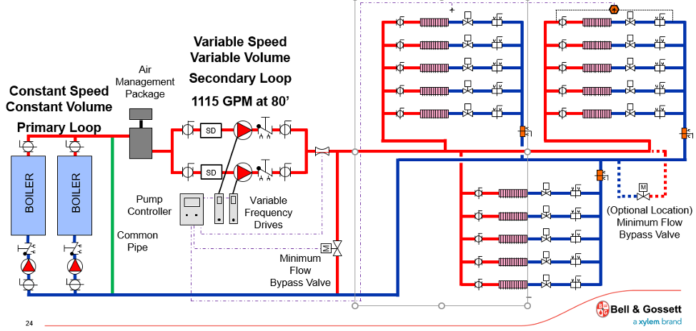
The system shown below was copied with permission from the Bell & Gossett online GoToWebinar “Sensored vs. Sensorless Pump Control: Which is Best for You”. This series is using several screenshots from that presentation with different subject matter.
The system is a primary-secondary system with three zones. Each zone has 5 terminal units. It may look complicated, but this system does not have many terminal units to balance. The engineer included a flow meter in the main, pump discharge valves for throttling and zone balance valves which will make the balance more accurate.
We will use this same system for the next two blogs. Part 2 will describe the procedures for a constant speed pumped system. Part 3 will be a variable speed system as shown below.
What is Proportional Balance?
Just 20 years ago, the normal balance method was referred to as “Read and Set” balance. A modified version of this method is called “Stepwise” by the National Environmental Balancing Bureau (NEBB). The read and set method started close to the pump and throttled valves to push the water out to the end of the system. This technique may result in all the over-heading and safety factor in pump selection being throttled out in the system.
Proportional balance is a method starting at the hydraulically farthest zone or the zone with the least amount of water. The contractor measures the percentage of flow rate available vs. the design flow rate. Then they throttle the next “farthest” balance valve and set it to the same percentage of its design flow rate as the first valve. This process continues all the way back to the mechanical equipment room or pump. When the balance is complete, all the valves are set at the wrong flow rate but are proportionally correct. As the pump discharge valve is throttled to design, all the balance valves will also change to the design flow rate.
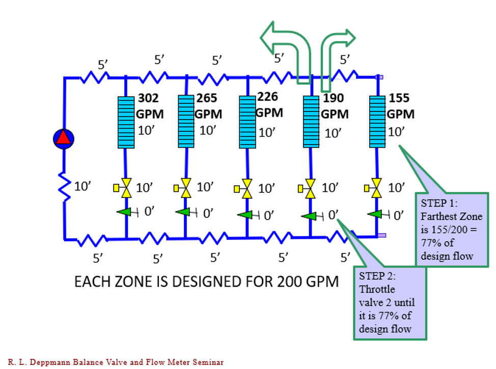
When balance valve 2 is throttled, most of the throttled 35 GPM will push back into the zones yet to be balanced. A small amount of flow will be added to the step 1 zone.
Proportional Balance Valve Steps
The following is a brief description of the steps in a proportional balance with some comments. This is not a complete balancing course. It is meant to provide the outline of what the balancer does. These steps follow many of the steps outlined in the NEBB Procedural Standards for Testing, Adjusting, and Balancing of Environmental Systems.
- Set all the balance valves and control valves to full open.
- Throttle the discharge pump valve to 110% of design.
- Comment: A VFD can be used to throttle. Sometimes the balancer is not allowed to touch the drive if supplied by another trade and not officially started up or turned over.
- Determine the order of the valves to be throttled from least flow to most flow. This may require an initial read of all valves. The seasoned balancer may skip some steps by reviewing the terminal unit schedule, the piping layout, and their experience.
- Start with the branch or zone balance valves. (Shown in orange above). Proportionally throttle each branch against the next closest zone before balancing the terminal units. In our example system, there are three branches to balance.
- Comment: Today, many engineers neglect to provide a branch balance valve. ASHRAE recommends a branch or zone balance valve on circuits with more than 25 terminal units. Review your ASHRAE Applications handbook 2019 – section 39.28.
- Once the branches are balanced against each other, move to the hydraulically farthest zone and the farthest terminal until and start proportionally balancing those units. Then move to the next zone or branch. Determine the worst terminal unit percentage of design and balance that zone.
- Comment: In our example system, there are 5 terminal units in each branch or zone. Normally, in the real world, there are many more terminal units in a branch.
- If at any time the flow rate cannot be achieved, go back, and open the pump valve a few percentages. Remember, if you change the setting of the pump, re-read the last balance valve percentage of design.
- When the balancing of terminal units is complete, set the pump at the design flow rate plus the allowance specified.
- Remeasure the valves, set the memory stop, and record results
- Comment: Some seasoned balancers may spot-check during this step.
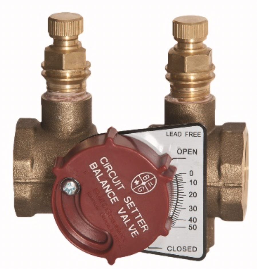
PICV and Automatic Balance Valves
Just a comment about automatic balance valves. Bell & Gossett and Griswold Controls both make manual and automatic balance valves. The automatic balance valves are pre-set to the design flow rate. When these are used, the balance contractor must read out the valves to find the one with the least amount of automatic throttle. This pressure drop, less the minimum valve drop, will be the amount of extra pump head to be eliminated by VFD throttling or impeller trimming.
Some engineers will use a branch automatic balance valve and terminal unit manual valves. This will get the flow in the right areas in complicated systems. Do not put two automatic balance valves in series with each other. Example: do not put an automatic balance valve in the branch of a zone with automatic balance valves on each terminal unit.
Part 2 will explain the throttle and trimming of the pump after the proportional balance is complete. For more information on types of balancing valves, visit our R. L. Deppmann Monday Morning Minutes website.