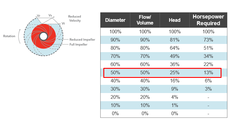
 The HVAC hydronic system is proportionally balanced per ASHRAE 90.1 energy standards. The proportional balance, when properly completed, will result in all the extra pump head across the discharge balance valve. The next step depends on whether the pump is constant speed or variable speed. Today, we look at the constant speed pumps and the trimming of the impeller.
ASHRAE 90.1 – 2013 and Impeller Trimming
ASHRAE 90.1 – 2013 is the standard used by many States for the State Energy Code. Section 6.7.2.3.3 says the system shall be proportionally balanced and then, for constant speed pumps over 10 HP, the impeller trimmed. The exception is stated as “when throttling results in no greater than 5% of the nameplate horsepower draw, or 3 hp, whichever is greater, above that required if the impeller was trimmed1”.
Centrifugal Pump Runout
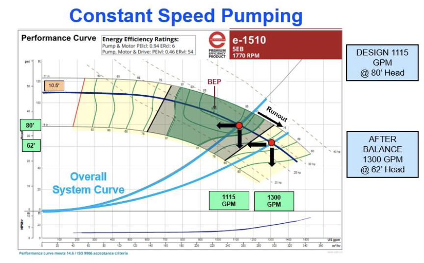
In part one of this series, Proportional Hydronic System Balance Process, we used an example Bell & Gossett pump. Once the hydronic system balance was complete, the pump was flowing more gallons per minute (GPM) than scheduled. Take a look at the pump curve.
The terminal unit balance is complete. The total flow rate is 1300 GPM which is 117% of the specified flow rate. The balance contractor now follows seven specific steps to complete the test and balance (TAB) hydronic report and offer the suggested impeller trim. Each step below will follow with the step in our example system.
- Read out the pump suction and discharge pressures and convert to pump differential in feet of head. Verify any Centrifugal Pump Gauge Readout Corrections for Hydronic Glycol Systems. Record all readings, not just the differential.
- Example: Suction is 12 PSIG. Discharge is 39 PSIG. Difference is 27 PSIG or 62 feet.
- Locate the pump curve of the model and RPM being read. Plot the pump head and read across to the impeller curve. Then read down to the flow rate. If possible, find another method to verify the approximate GPM.
- Example: Looking at the curve above, we verify the RPM of the curve and motor RPM are close. The flow rate is 1300 GPM. This was verified using a Badger Preso flow meter on the main supply header (Break The Tie! Preso Ellipse Flow Meters for HVAC Hydronic Mains)
- Throttle the pump discharge balance valve until the pump differential reads what is required for the design flow. Record the readings. If the pump balance valve has pressure ports, record the throttled discharge valve differential and the setting of the valve. This will give us a second reference point in the report to determine the possible impeller trim.
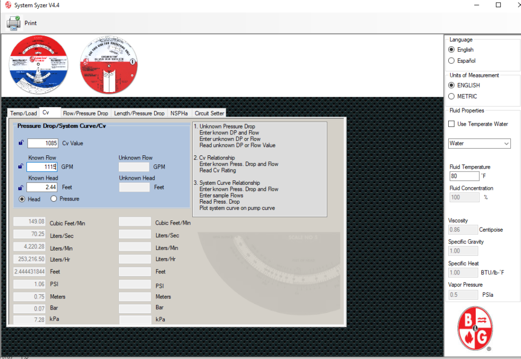
- Example: This pump has a B&G 3DS-8S full port triple duty valve with a full open CV of 1085. The pump was throttled until the suction reading was 10 PSIG and the discharge was 44 PSIG. This is about 78 feet of head. The triple-duty valve was throttled to about 26 percent open and the differential across the valve was 37 feet.
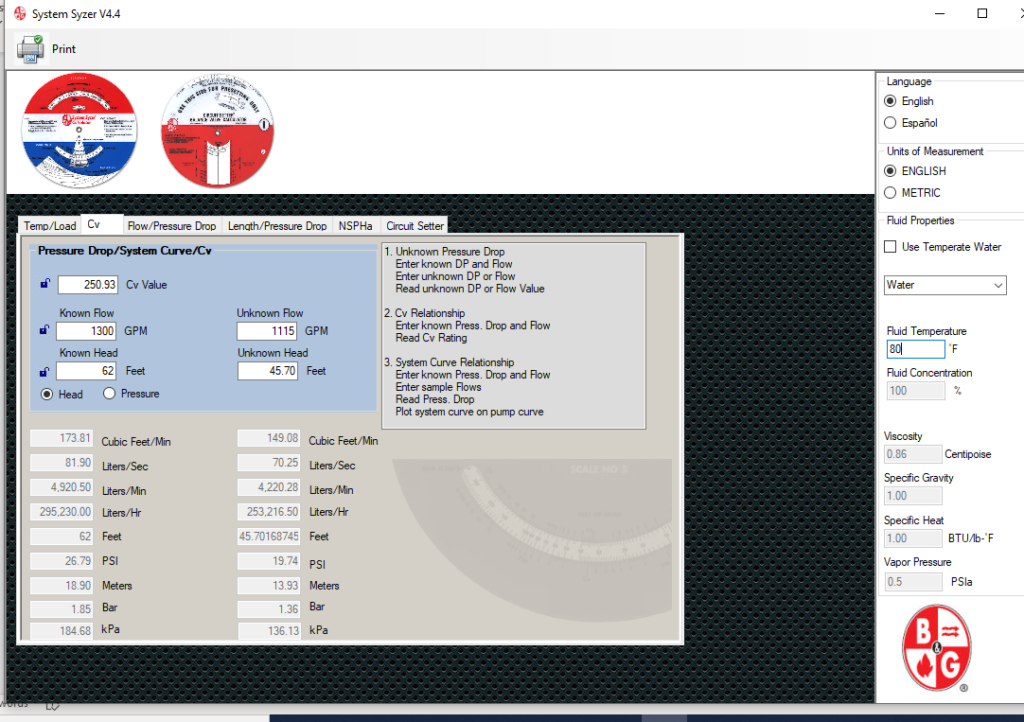
- Verify the required pump head. Use the B&G electronic System Syzer CV. Enter the known flow rate and head with the pump discharge valve fully open. This is called the known flow and head. Enter the required flow rate under unknown flow and read the required pump head at the specified flow rate.
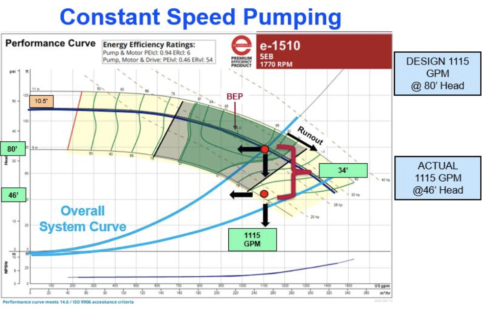
- Review the pump curve to determine what impeller is needed for the design flow rate at the required pump head from step 4. This could be verified by putting the design flow rate and new head into esp-Systemwize, select the same pump, and view the recommended impeller.
- If available, verify the calculated head reduction by comparing the throttled triple duty valve pressure drop with the full open pressure drop at the design flow rate using the B&G system syzer CV tab once again. Look up and enter the CV of the discharge valve. Enter the design flow rate under known flow. Read the full open pressure drop under the known head. Remember to select the feet button rather than PSIG.
- Apply a safety factor and report a suggested impeller trim. Once the impeller is trimmed, we cannot glue it back on. The ASHRAE standard listed above suggests a 5% horsepower tolerance. That seems like a nice cushion. The triple-duty valve supports the trim listed above since it suggests more than 34 feet of excess pump head. This is where most balance contractors will leave the decision up to the engineer. Run the esp-Systemwize program to find that magical 10% safety on the horsepower OR just call your B&G rep and ask them to do it for you.
- Example: We ran the esp-Systemwize program and found the following.
- At the 46 feet of head, this pump indicated a 9.25” impeller and 20.3 brake horsepower (BHP).
- We raised the head until the same pump gave us 20.3 X 1.1 = 22 BHP. At 52 feet of head and a 9.5” impeller, the 1115 GPM will use 22.3 BHP. We recommend trimming this impeller from 10.5” down to 9.5”. Once it is trimmed, the triple duty valve should be opened to full open (100%). All the control valves should be returned to the fully open position and the pump read out again and a final report written.
- Example: We ran the esp-Systemwize program and found the following.
Most pumps are oversized. Most pump discharge valves remain throttled after the balance. The reason for this is “you can’t glue it back on.” Variable speed pumps solve this problem and they save energy. The next R. L. Deppmann Monday Morning Minutes will look at trimming by using the variable frequency drive.
1 ANSI/ASHRAE/IES Standard 90.1-2013 page 62.

