Printer Friendly (PDF)
Centrifugal pumps operate at the intersection of the pump curve and the system curve. Last week we developed the system curve for an example closed hydronic heating or cooling system. Today, the R. L. Deppmann Monday Morning Minutes reviews the basic differences between two-way and three-way valves before we look at their effects on the control curve.
Closed System Curve Review
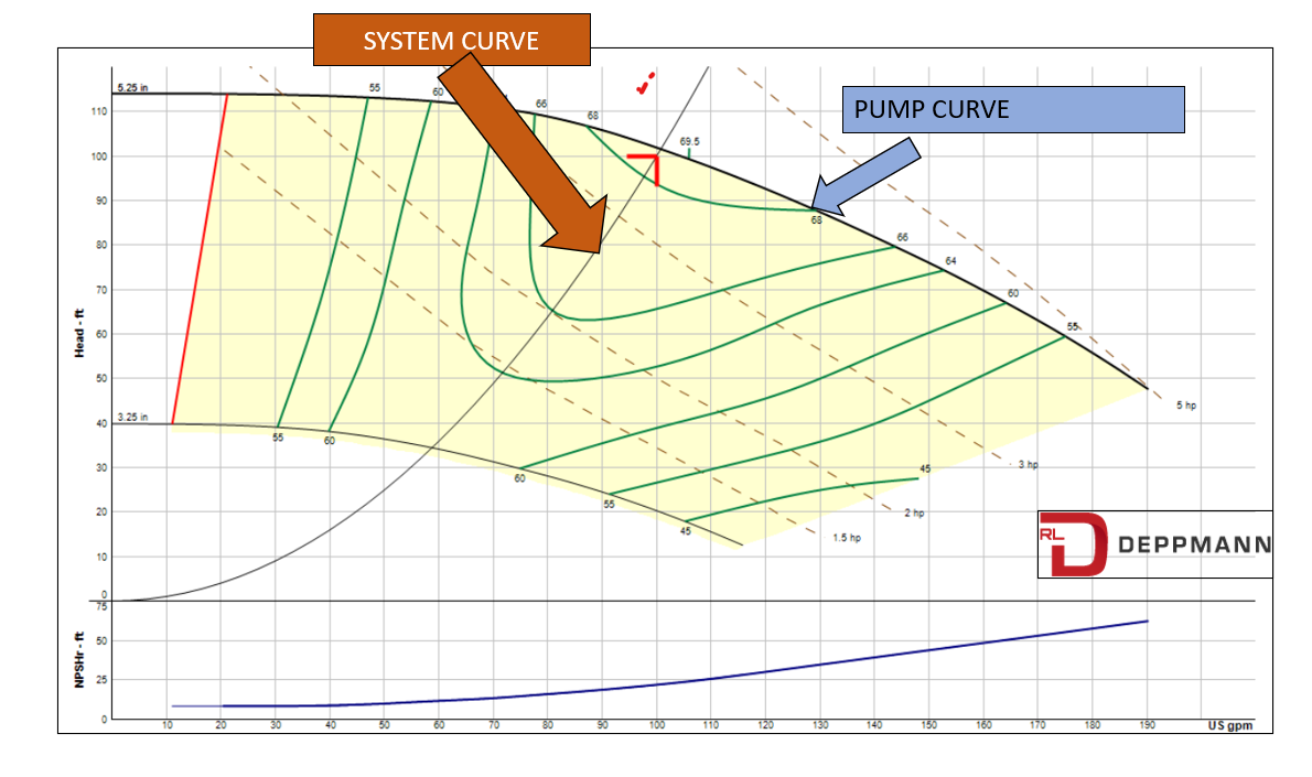
Last week, in Closed System Curves in HVAC Hydronic Systems (Part 2) we developed the system curve shown on a constant speed pump curve above. The system curve is shown with the simple capacity numbers of 100 GPM at 100 feet. All the control valves are wide open, and the system is balanced to the design flow rate. THE PUMP WILL OPERATE AT THE INTERSECTION OF THE PUMP CURVE AND THE SYSTEM CURVE.
What happens when the internal temperatures in some of the spaces within the building rise or fall? Control valves will adjust to reduce the flow rate and reduce the heat transfer of the terminal unit. What happens to the system curve?
Please note that you may be thinking about variable speed pump curves while I am using a constant speed pump curve. We will address the variable speed application after the basics are understood.
Three-way & Two-way Control Valves in Hydronic Systems
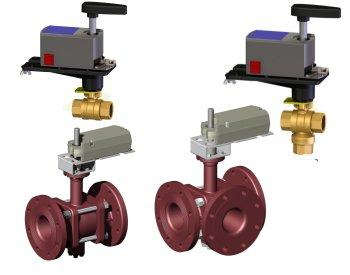
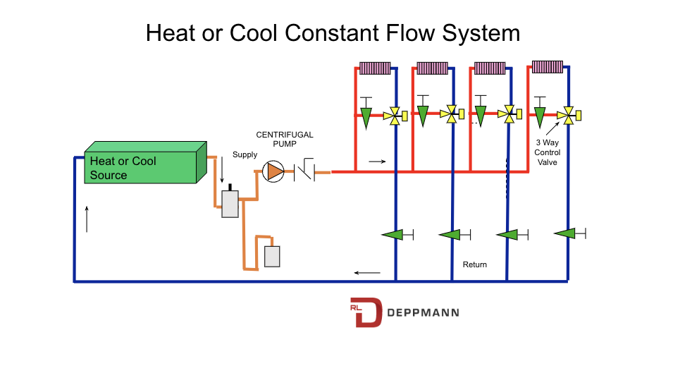
The photo above is from Actuated Valves | Griswold Controls. The two valves on the left are two-way control valves and the valves on the right are three-way control valves. How do we represent these in system sketches? If you look at the system representation at the start of this article, you see the system has a single pump with (3) – two-way valves and (1) – three-way valve.
The goal of the control valve in hydronic systems is to react to a temperature control signal and reduce the flow rate through the coil or terminal unit.
Three-way Control Valve Operation
Decades ago, most hydronic systems had three-way control valves at most of the terminal units. Look at this simple representation of a typical system utilizing a three-way valve.
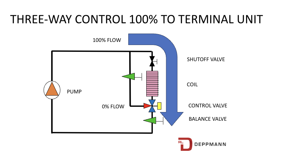
When the control system is calling for 100% capacity from the coil, 100% of the flow rate is forced through the coil by the control valve. In this example system, the bypass port, shown in red, is closed. The ports shown in blue are open.
A key point to remember. Control valves and their ports are often different depending on brand and operation. Although we show the bypass port on the side and the common port on the bottom, this is just for representation. Make sure you follow the valve manufacturer’s proper piping procedures before showing or installing a control valve.
When the space temperature is completely satisfied, the three-way valve representation would look like this.
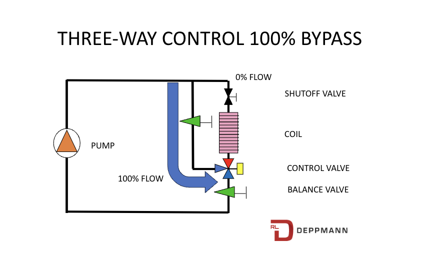
A subtle but important thing to note is the pump flow rate. The pump is flowing 100% of the flow whether the control valve is 100% to the coil or 100% in bypass. This is important to understand. Way back in time, when television was in black and white, pumps, chillers, and boilers did not like variable flow. Terrible things could happen. The engineer designed the system so the pump operation remained constant regardless of the controls position.
The balance valves were adjusted during commissioning so the flow was the same in bypass as it would be when 100% through the coil.
There are some of the valves that are either open to the coil or closed to the coil. The three-way valve used as an example is a fully modulating valve. At partial flow, some of the water would flow through the coil of terminal unit and some would bypass the coil. The control valve would modulate position to keep the space at the right temperature.
The system curve did not move at all or little. In our example system from last week, the flow would always be 100 GPM at 100 feet of head.
Two-way Control Valve Operation
The two-way control valve operation is a lot simpler. Once again, the valve may be an on-off type which is either open or closed. We are assuming the control valve used here is fully modulating.
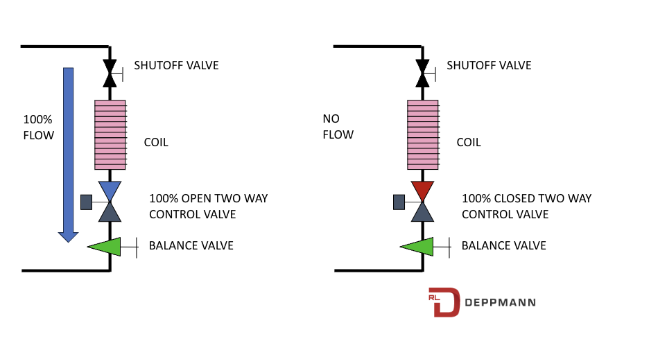
The representation on the left is fully open and the one on the right is fully closed. The valve may modulate between those two points. The pump flow rate may be anywhere between 100% design flow and 0% design flow. At zero flow rate, the pump is operating with a closed discharge and that is not good. We would never want to operate at this point. In order to avoid a no flow condition, we would do something in the system to prevent that.
Closed System Curves with Two-way Valves
So, what does the system curve do in a two-way modulating control valve application? We know it starts at 100% of the design flow rate. We know that it ends with 0% of the design flow rate. As the two-way valves modulate towards closed, the pressure drop through the valve is increased. This causes more pressure drop at a lower than design flow rate. We change the look of the system curve during operation.
Let’s open the Bell & Gossett ESP Systemwize pump selection program and look at some system curves. Here is what the system curves look like.
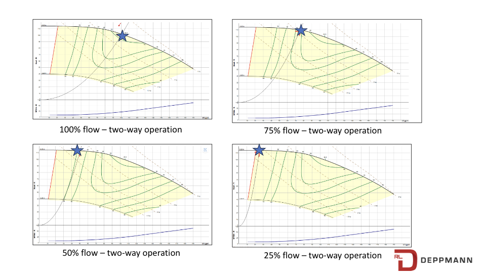
The system curve gets steeper as the control valve closes. The operating point moves back on the curve and heads toward 0 GPM. The pump horsepower requirement is reduced and we are wasting energy. Wasted energy in constant speed variable flow applications is why variable speed pumps are often used. Next week we will look at variable speed pump curves.