Printer Friendly (PDF)
 Our industry spends tons of time talking about variable speed HVAC control curves and the effect on the minimum speed and cost analysis of variable speed pumping systems. Control head & curves in plumbing systems are more complicated than closed hydronic systems. They also play an important role when choosing the number of pumps in a pressure booster system.
In the last R. L. Deppmann Monday Morning Minutes, Domestic Water “Pressure Booster Pumping System” – Building Flow Profiles, we presented a short discussion making it clear that the typical flow rate is normally a fraction of the design flow rate in most plumbing systems. This fact, coupled with a varying, relatively high control head, will impact your choice of the capacity of each pump in a domestic water pressure booster.
What is the Control Head and Control Curve?
I admit it! I am a hydronic and pump geek! As a result, I can sometimes start conversations assuming everyone has the same 44 years of pumping experience and the focus I have enjoyed. The reality is that most engineers have to know about all facets of heating and cooling. plumbing, and process systems while I am much more focused. So, I will assume a quick review of the terms “control head” and “control curve” may help.
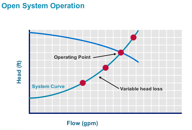
The control head is the minimum pump head the pump should ever produce. There is a discussion of this in a previous blog HVAC Variable Speed Pump Control Head.
In hydronic closed systems, it is the pressure drop across the farthest circuit. If the farthest valve opens and needs flow, the pump head should be able to satisfy that circuit. As more valves open and there is more friction loss, the pump will speed up to maintain that pressure differential at the last circuit. So the control head is a point at 0 GPM at the head in feet required to satisfy that last zone. It is similar in plumbing… but with a twist.
Control Head in Plumbing Systems
As mentioned above, the control head is the pressure required at 0 GPM to satisfy the furthest zone downstream from the location of the pressure sensor. If we use ASHRAE 90.1 standards, the pressure sensor should be located near the farthest fixture. That will be the last flush valve on the top floor of the building. Let’s use the example we started a few weeks ago at Domestic Water “Pressure Booster Pumping System” – Discharge Pressure; The pressure sensor located near the flush valve requires 35 PSIG and the elevation to the top floor is 120 feet from the pressure booster. If we don’t include friction loss, the pressure required is 52 PSIG (120/2.31) plus 35 PSIG or 87 PSIG. Now we subtract the suction pressure and that gives the maximum control head in PSIG.
In our example blog; Domestic Water “Pressure Booster Pumping System” – Suction Pressure, the minimum suction pressure is 37 PSIG. The maximum control head is 87-37=50 PSIG. This assumes we located the pressure sensor at the furthest fixture. Let’s look at a single pump and the load profile for the 300 GPM in our example.
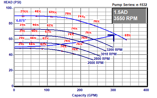
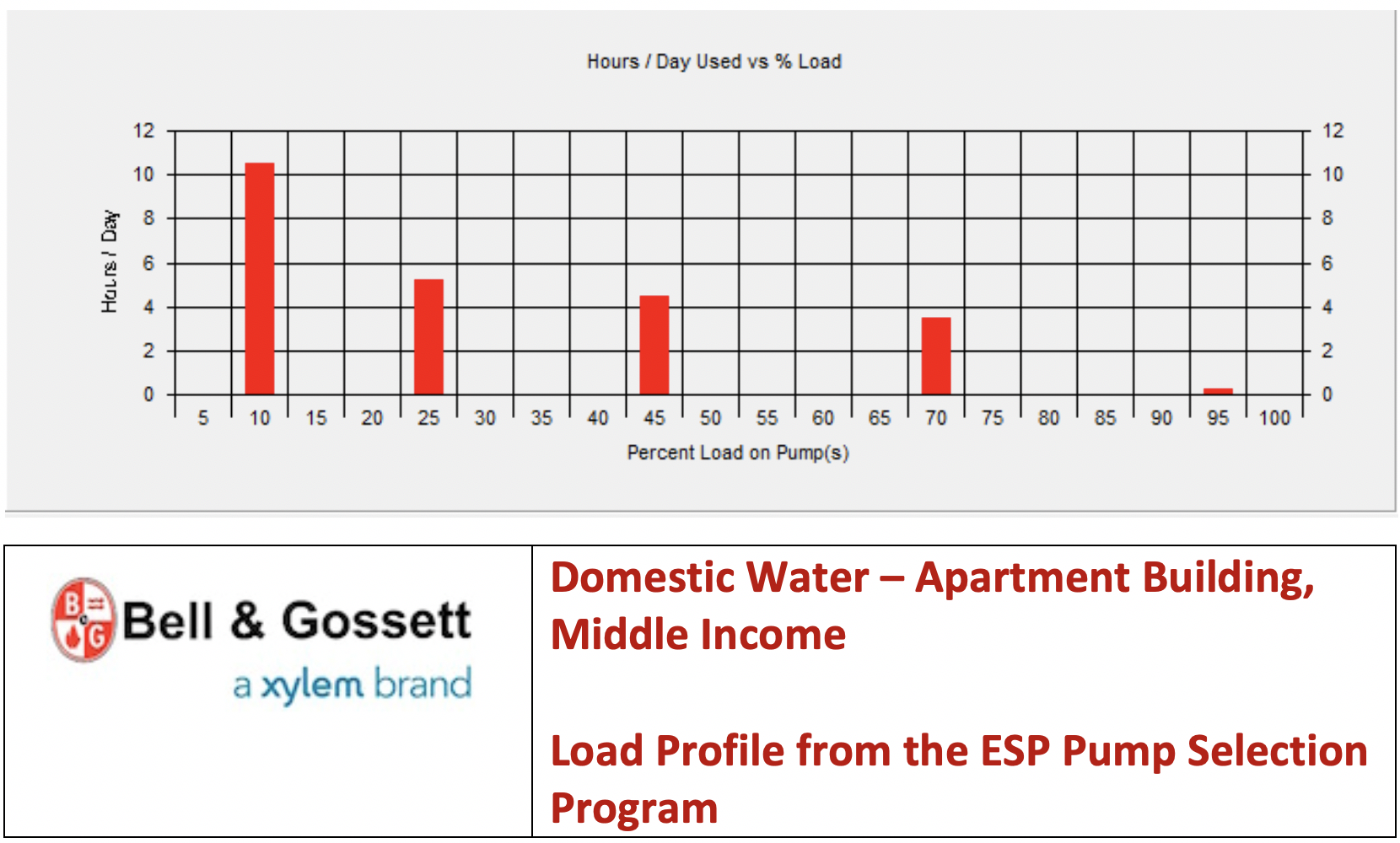
Note that when the suction pressure rises, the pump differential needed will drop and the curve will change a bit. Based on the load profile above, over 10 hours per day, the demand will be 10% of the 300 GPM design or 30 GPM. We’ll operate at this flow almost 50% of the time. Now, look at the control curve. At 30 GPM this pump will operate at around 2600 RPM, but the efficiency will be about 30%!
If I told you I’d give you a pump that will operate at 30% efficiency would you be satisfied? This is where multiple pumps in parallel are recommended in variable speed pressure boosters and that will be the subject of the next R. L. Deppmann Monday Morning Minutes.
Catch up on recent Pressure Booster Pumping System posts: