Printer Friendly (PDF)
 In the last R. L. Deppmann Monday Morning Minutes we looked at the discharge pressure calculations for a pressure booster. Today, we turn our attention to the suction pressure and total design differential head of the pressure booster.
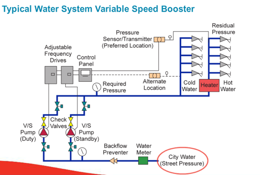
Pressure from the Municipality
The first suction pressure piece of information we need is the amount of pressure from the municipality. The municipal pressure is stated in terms of static pressure and residual pressure. These are terms fire departments use for their hydrant. If you call the city water department or fire marshal, you could give them the nearest intersection of the building and ask for the static pressure or maximum pressure and the residual or minimum pressure. This would normally be at the hydrant so you must make allowances for the length of the main and its pressure drop as well as any elevation changes. Often times, the friction is low enough that the city pressure is used as the pump suction, but you must be comfortable with the design before you do that.
We started an example in the last Monday Morning Minutes Domestic Water “Pressure Booster Pumping System” – Discharge Pressure. Let’s assume for our example that the static pressure is 60 PSIG and the minimum pressure is 45 PSIG. In this example, we are not comfortable guessing the pump suction pressure, so we will do the calculations. There is a 10 foot drop to the pumping system in the basement and 50 feet of pipe.
Water Meter and Backflow Preventer
The water meter and backflow preventer are two devices normally found in front of the domestic water pressure booster. Their pressure drop will reduce the available pressure to the suction of the pressure booster pump.
Let’s assume for our example apartment building that the design flow rate is 300 GPM. We checked the Badger Meter water meter being used and it has a 3 PSIG drop at the design flow rate and 0 PSIG drop at 0 GPM.
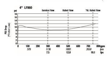
The reduced pressure zone type backflow preventer has an unusual pressure drop curve. Here is a Watts model flow/pressure drop curve.
https://www.watts.com/dfsmedia/0533dbba17714b1ab581ab07a4cbb521/34444-source
You will notice that at the design flow rate of 400 GPM the pressure drop is 8 PSIG but at shutoff the pressure drop is 11 PSIG. In general the pressure drop at “0” GPM will be about the same or slightly lower than the pressure drop at design. It is good to check the product you base your design on and use those numbers.
Unusual Pressure Drop Items in the Suction Piping
Occasionally there may be an unusual item in the suction piping. These are rare, but can surprise you if you do not include them in the calculations. An example would be an iron filter or softener. Our example will assume there in no additional item in the suction piping.
Using the R. L. Deppmann Pressure Booster Tool
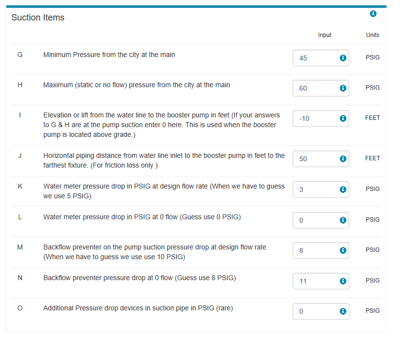
If you go to our website plumbing page R. L. Deppmann Plumbing Website and use the “design tool” selector in the pressure booster section, we can enter the suction items just as we did the discharge items in the last MMM.
Here is a screen shot of the suction section:
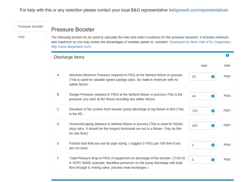
For reference here are the discharge numbers from last week:
The tool will do the calculations for you and give you the scheduled capacities:
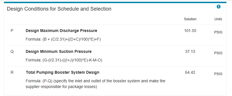
You should schedule the required discharge pressure and the minimum suction pressure. Let the manufacturer include the package pressure drop to provide the correct pump head. We see in our example we will need about 65 PSIG of differential from the package.
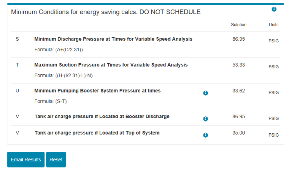
I also included a section which is helpful but not scheduled. We can see that we need 65 PSIG in the worst case, but there will be times when the booster system will only need 34 PSIG. This is a great application for our variable speed pressure booster which will save a lot of money. Also included is the tank charge pressure if the tank is at the booster pumping system discharge or located at the top of the system near the last fixture. For more information on the tank location visit Hydropneumatic Tanks for Variable Speed Pressure Boosters.
If you want a copy of the calculations for your record, simply click on email results – we don’t ask for much information. The Job Title is for your reference.

Next week, the R. L. Deppmann Monday Morning Minutes will look at the number of pumps required for the pressure booster.