Printer Friendly (PDF)
For the last two weeks, R. L. Deppmann Monday Morning Minutes has explained how the float and thermostatic steam trap operates, offering some tips for troubleshooting problems in the field. This week we select a trap for the example used in this steam and steam heat exchanger basics series.
 Our example heat exchanger has a capacity of 2,000 pounds per hour (PPH) with 10 PSIG steam pressure to a modulating steam control valve. We will assume the steam pressure to the heat exchanger is 5 PSIG after the control valve pressure drop. We learned in the last two blogs that a float and thermostatic steam trap is the correct choice for this application.
Before we select the trap, I want to answer this question: Why Hoffman? Hoffman, a Xylem brand, manufactures many quality steam traps. The F&T trap starts with hardened stainless steel (SS) seat and pins, SS float, lever, and thermostatic element. All of this is wrapped with a cast iron 30,000 PSI tensile body with grade 5 bolts. A durable, quality product for this aggressive duty.
Safety factors when selecting the Hoffman steam trap.
The selection starts with an appropriate safety factor applied to the 2000 PPH load. In modulating heating load applications, we recommend you use a minimum of a 1.5 safety factor. One reason there are safety factors applied to steam trap selections is the catastrophic results if a trap is undersized. In part 8 of this series, we described the operation of the trap. If more PPH of condensate enters the trap than it is rated for, condensate will back up and damaging water hammer may occur. How can this happen?
Let’s start with the heat exchanger itself. There are fouling factors applied to shell and tube heat exchangers during the selection process. In an earlier R L Deppmann Monday morning Minutes article called Heat Exchanger Fouling Factors I explained how fouling factors could increase the surface area by 35% or more. In a cold startup, the log mean temperature difference (LMTD) of the heat exchanger could be twice as much as the design which again increases the PPH capacity of the heat exchanger. Both of these reasons may cause the heat exchanger or heating coil to use more PPH of steam if the steam control valve can pass it.
Steam control valves are sized based on CV, which is derived from the capacities needed. It is rare that the required CV is met exactly — there is always some oversizing. In addition, during times of startup when the heat exchanger or coil can take more capacity, the control valve can provide 10-15% more by dropping the outlet pressure. Add to that the effects of wet steam or superheat and the 1.5% safety factor does not seem so large. I’ll talk more about this in later articles about pressure reducing valves.
Selecting the Hoffman float and thermostatic steam trap.
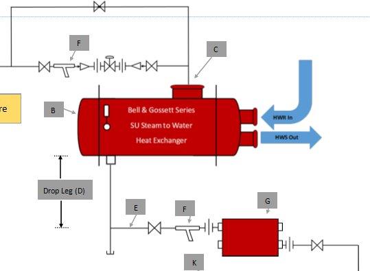
Our example requires 2000 PPH in a low pressure 10 PSIG system. The 1.5 safety factor gives us a rated capacity of 3000 PPH. We use a differential of ½ PSIG. This differential is selected because the pressure in the shell may drop as low as “0” as discussed above and in the earlier Condensate Drop Leg and Pipe Size: Steam and Steam Heat Exchanger Basics Part 4 blog article. Let’s select a steam trap using the Hoffman Specialty Catalog HS-900F.
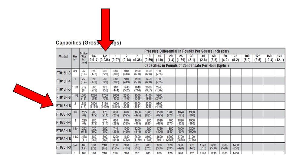
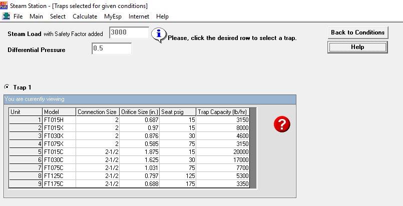
We will use a Hoffman model FT015H-8, which is a 2” “H” pattern float and thermostatic steam trap. The same model may be selected using the Hoffman steam trap selection software available through our selection and design tools web page link.
Next week the R. L. Deppmann Monday Morning Minutes will look at the strainers in steam and condensate systems.