Printer Friendly (PDF)
A few weeks ago we discussed the steam pipe size entering a shell and tube heat exchanger, also called a convertor. This week we turn our attention to the condensate outlet. A customer recently asked, “I was told to pipe a 14-inch condensate drop leg from the bottom of a steam-to-water heat exchanger to the F&T trap inlet. What happens if I only have room for 10 inches instead of 14?”
Condensate Steam Hammer
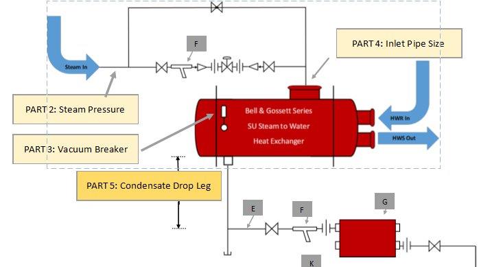
The question regarding the “C” dimension, or condensate drop leg, on the sketch above is important for properly draining the condensate from the heat exchanger.
If steam tries to travel through condensate, it causes water hammer damage as the steam adds energy to the water and it flashes back into steam. It’s important to make sure all of the condensate is drained out of the heat exchanger when the steam valve opens.
There’s a modulating control valve in most HVAC applications using shell and tube heat exchangers. The control valve is normally sized for a 50% drop in pressure at the rated PPH design capacity. When the valve is fully open, that reduced steam pressure is in the shell. Once the valve closes, the vacuum breaker opens and the pressure in the convertor goes to zero PSIG. At that point, the only motive force to move condensate through the trap is the pressure caused by elevation. Since the trap has a pressure drop, we rely on the “C” distance to provide the head required to overcome the pressure drop in the trap.
Condensate Drop Leg Length
One PSIG of water pressure will lift water about 2.3 feet, or 28 inches. If we had a column of water 28 inches high with “0” PSIG on top, a pressure gauge at the bottom would read 1 PSIG. If we fill the drop leg to the trap with 14 inches of water, there will be ½ PSIG pressure at the trap inlet.
In low-pressure systems, we normally specify the trap to be sized at ½ PSIG differential when we have a gravity return out of the trap with no lift. Now we know why! We don’t have to depend on steam pressure to make sure the trap drains, because the “C” dimension provides the pressure we need.
If you make the drop leg 10 inches instead of 14, the motive force across the trap will be 10/28 or 0.36 PSIG. If we size the trap for 1/3 PSIG pressure drop, this will still be okay. Conversely, if you pipe 28 inches instead of 14, you have almost a pound of pressure at the trap. This won’t cause a problem at all because more is better. In fact, if you know you have 28 inches available, the trap size likely will be smaller.
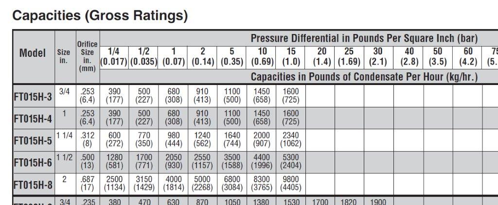
For example, assume the system is low pressure, under 15 PSIG, and the trap is sized for 900 PPH of condensate. The chart below requires a 1-1/2 inch model FT015H-6 trap when sized at 14 inches of drop leg to the trap. If you have 28 inches available, the trap can be sized at 1 PSIG. This allows us to select a 1-1/4 inch model FT015H-5. You save money and avoid over-sizing the trap.
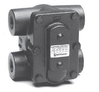
While we’re selecting this Xylem Hoffman F&T trap, you may notice a special advantage for contractors. The Hoffman “H” series of traps has two inlets and two outlets. Imagine being able to choose the direction into the trap so the pipe continues in one direction. Imagine also that the second outlet could have an elbow and a shutoff valve as a test port. You save materials and labor and space with the Hoffman “H” style trap.
Next week we’ll address the condensate pipe size.
Discover more on our Heat Exchanger Series below:
Part 1: Understanding Steam and Steam Heat Exchangers
Part 2: Why Use Low Steam Pressure?
Part 3: Vacuum Breakers: Steam and Steam Heat Exchanger Basics
Part 6: Steam Condensate Pipe Sizing
Part 7: Steam and Condensate Pipe Sizing Health Care Example