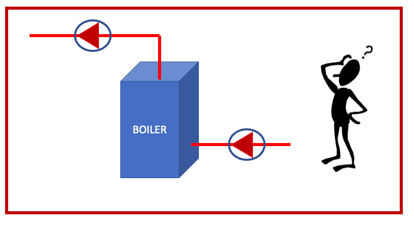
 We recently received several calls for our recommendation on whether to pump into the boiler or out of the boiler in a primary variable heating system. It is interesting that this subject is up for discussion, and it may be fueled by some of the boiler manufacturers. The answer is not simply about the pump. It involves other equipment.
Does the pump care where it is located in a low pressure closed hydronic system?
Statement 1: The pump does not really care where it is located in a low pressure closed hydronic system.
The centrifugal pump will develop a differential pressure which will cause flow in the system. That developed design differential pressure will be the greatest at full speed for the impeller provided. The shutoff head or differential pressure with pump discharge valve closed will normally be higher than anywhere else on the curve.
The pump will add the pump head to whatever pressure is at the suction inlet, regardless of where it is at in the system. The discharge will be the combination of the inlet pressure plus the pump differential pressure.
Does the pump care where it is located in relation to the expansion tank in a closed hydronic system?
Statement 2: The pump is very concerned about where it is located in relation to the expansion tank and wants to pump away from the tank.
The place where the expansion tank is connected to the system is called the point of no pressure change. At this point in the system, for any given temperature, the pressure will not change whether the pump is on or off.
It is extremely important, especially in commercial systems, that the tank be located near the pump inlet. Point of no pressure change is important. If you are not convinced that the pressure will not change at this point for a given temperature, you can check out the B&G TEH-1196C Air management for closed hydronic systems and our video Point of No Pressure Change – Expansion Tank.
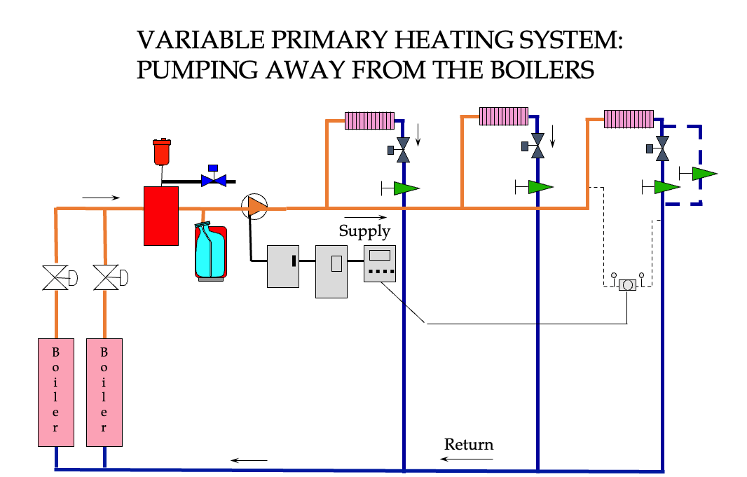
Locating the Primary Variable Pump on the Outlet of the Boiler
The image above shows a primary variable system with the pump pumping away from the boilers and away from the point of no pressure change. The boilers have 2-way on-off valves per ASHRAE 90.1 energy standards. For this example, the pump will add the differential head pressure to whatever the expansion tank pressure is at a given temperature.
The advantages of this location are many. The expansion tank cold fill pressure is the lowest pressure in the system. The pump discharge pressure is the highest pressure, and that pressure is available to assist in system air removal. The air separator is properly located at the lowest pressure point and highest temperature point in the system to maximize performance
The disadvantage is a concern voiced by some boiler manufacturers’ representatives. The boilers are seeing the lowest pressure in the system. When the boilers have a larger pressure drop, there may be a concern. The manufacturer of some boilers may indicate a concern or even a requirement that the pumps pump into the boiler depending on the system type. They are concerned about minimum pressure through the entire boiler. I will address this later in this article.
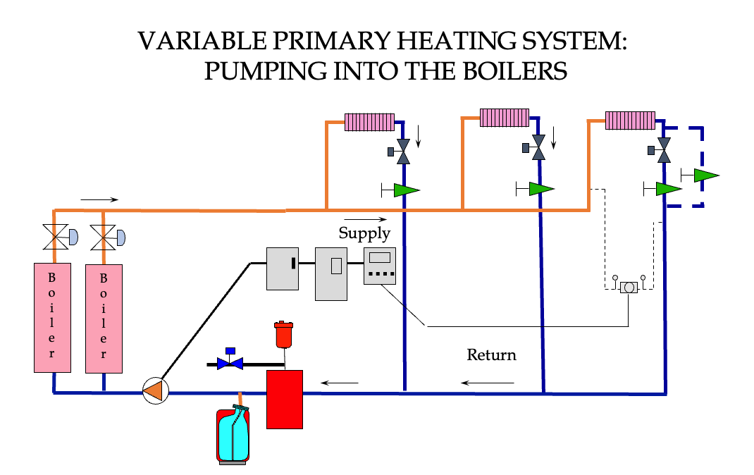
Locating the Primary Variable Pump on the Inlet of the Boiler: Should We Do It?
The image above shows us pumping into the boilers. We relocated the expansion tank to be near the pump suction. If each boiler had its own pump and check valve, the on-off valves would not be needed.
Advantages: Now the pump discharge is the highest pressure, and it is also providing the highest pressure at the boilers. The system is still seeing a high pressure for air removal. It is less pressure than the previous pump location but still good enough.
Disadvantages: There are two issues here: air separation and the relief valve setting. The air separator is no longer located at the highest temperature. It is at the return which is the lowest temperature. It will take more passes to remove the air. In addition, the extra air removed in the boiler due to higher temperatures will pass through the system before the air separator.
The other major disadvantage has to do with the relief valve. The relief valve will have to be set at the maximum expansion tank pressure used in the expansion tank selection PLUS the pump head at full speed. This may limit the choice of boilers if the pressure is higher than the boiler rating. It may cause the expansion tank to be larger if the maximum pressure in the tank sizing is reduced to accommodate the pump head. If the pump head and fill pressure are both high, the tank might become unmanageable in size.
Another big disadvantage shows up in the boiler pressure at the relief valve. Now the pressure in the boiler and, therefore, the relief valve pressure are tied to temperature and the pump head. There could be a condition where the pump speed is low, but the system temperature is high. The system could see higher temperatures than design but not have the relief valve discharge.
Example System: Expansion Tank Sizing
Let’s use a system example with 2000 gallons of water with a design of 180⁰F to 140⁰F. We will assume a fill pressure of 20 PSIG. Assume the boilers we use will have 100 PSIG relief valve set pressures. The pump head is 120 feet at design. We will use the esp-Systemwize program from B&G to size the tanks.
Tank selection for pumping away from the boilers. Fill pressure 20 PSIG. Maximum pressure 90 PSIG. The 90 PSIG is the 100 PSIG relief valve less 10%. Visit part 3 of our expansion tank sizing blog for more detail. The tank sizing looks like this.
The tank will be a B&G B400 which is 30” x 50” high.
Tank selection for pumping into the boilers. Fill pressure 20 PSIG. Maximum pressure 38 PSIG. The 38 PSIG is the 100 PSIG relief valve less 10% less the 52 PSIG pump head. Visit part 3 of our expansion tank sizing blog for more detail. The tank sizing looks like this.
The tank will be a B&G B800 which is 32” x 76” high.
When pumping into the boilers, what happens if the boiler is in a runaway condition, but the pump is at minimum speed and 10 PSIG? The B800 tank will now keep the pressure below 80 PSIG even if the boiler is in a run-away condition and the system temperature is 240⁰F!
Getting dangerously close to the limit of the low-pressure boiler code. Under these conditions, we are relying on the boiler temperature limit controls to protect the system. The ASME code recognized pressure relief valve is no longer engaged as a safety device.
Conclusions About Pumping into the Boilers in a Primary Variable System
Statement 3: The preferred location of the pump in a primary variable heating system is on the outlet of the boilers. If the boiler manufacturer requires the pumps located pumping into the boilers, the engineer should change the design to a primary secondary system.
Variable primary-secondary boiler systems and pump location will be the subject of the next R. L. Deppmann Monday Morning Minutes.


