Printer Friendly (PDF)
OK. I get it! Parallel pumping is a design technique I should review on most of my projects where first cost and energy cost are client considerations. How can the engineer create a simple specification for parallel pumping which may be used over and over on projects? This is the subject of today’s R. L. Deppmann Monday Morning Minutes.
When Should I Consider Parallel Pumping?
Parallel pumping can save you both energy costs and construction costs. The summary is that parallel pumping should be reviewed in variable flow systems:
- anytime a single pump is over 30 HP
- anytime the system is designed for future capacity
Over the last several articles linked below, there were several examples provided. You may read them for more explanation.
Scheduling of Parallel Pumps
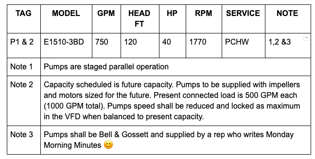
All pump schedules should indicate the operating pumps vs. the standby pumps. Example Note 1: P1 & P2 operate in staged parallel mode. Example 2 Note: P1, P2, and P3 operate in staged parallel mode with one standby. Example 3 Note: Pumps P1,P2, and P3 are 50%-50%-50% parallel pumps.
The other note to provide on the schedule would identify any future design condition.
Specification of Parallel Pumps
The pump specification can remain as you would normally show in the documents. The real change would be in the control of the pumps. There are three typical control schemes:
Fixed DP sensor out in the system
Theory:
This is the standard DP sensor (area control) with a BMS signal back to drives. In a parallel application, the end of curve operation most likely will be an issue. We want a flow meter in the main (example: Badger Mag meter). This is coupled with a pump curve algorithm, programmed by the pump manufacturer, into the drives to avoid end of curve problems. This is accomplished without artificially raising the DP set point.
Drawings:
Add a flow meter in the return main from the system with a signal to the drives. This can be the BMS flow meter used for other purposes with the signal coming to the drives from the BMS panel.
Spec:
“Parallel pump variable frequency drives shall include a pump curve algorithm to adjust and stage the number of operating pumps to satisfy both the DP sensor setpoint while providing end of curve protection. Drives shall be Bell & Gossett IPC which must meet the VFD (variable frequency drive) section of this specification except for the brand name.” Drive specification with the end of curve algorithm
Sensorless Pump Control
Theory:
This method involves the use of a quadratic equation (curve control) built into the pump manufacturer’s supplied drives. The drives may be wall-mounted or mounted to the pumps depending on the engineer’s code and code clearances required. A separate parallel pump controller is provided
Drawings – assumes wall mounting:
Show a separate wall-mounted B&G PPS parallel pump controller panel located near the drives. This panel will provide the staging controls to the drives. The power wiring is introduced into the PPS controller. Both power and control wiring is shown between the PPS panel and the drives. This wiring is included if the packaged pumping system is provided. A separate means of main disconnect must be shown by electrical. Alarm and notification to the BMS is from the PPS.
Spec:
The pump control shall be sensorless with the logic contained in the Bell & Gossett series ITSC variable frequency drives. A separate B&G series PPS parallel pump controller shall stage the pumps and protect the pumps from operation off the end of curve. Contact R. L. Deppmann for the drive specification and PPS specification.
Fixed DP with valve position reset
Theory:
This is an option that involves verification of control valve position and changing signal to the drive until one valve is close to 100% open. In a parallel application, the end of curve operation most likely will be an issue. We want a flow meter in the main (for example: Badger Mag meter). This is coupled with a pump curve algorithm, programmed by the pump manufacturer, into the drives to avoid end of curve problems. This is accomplished without artificially raising the DP set point.
Drawings:
Add a flow meter in the return main from the system with a signal to the drives. This can be the BMS flow meter used for other purposes with the signal coming to the drives from the BMS panel.
Spec:
“Parallel pump variable frequency drives shall include a pump curve algorithm to adjust and stage the number of operating pumps to satisfy both the control signal while providing end of curve protection. Drives shall be Bell & Gossett IPC which must meet the VFD (variable frequency drive) section of this specification except for the brand name.” Drive specification with the end of curve algorithm.
Parallel pumping is a valuable option for your clients. Give parallel pumping a try and let us know if you need another set of eyes on the design and selection of B&G equipment.
HVAC Hydronic Series:
Article 1: What is parallel pumping and why do it?
Article 2: Selecting parallel pumps and the curve
Article 3: Controlling parallel variable speed pumps
Article 4: Parallel pumping and standby capacity
Article 5: Parallel pumping and cost
Article 6: Parallel pumping specifications