Printer Friendly (PDF)
The historical view of parallel pumping was to make sure all the staging points landed on the single constant speed pump curve. This avoided operating at a point off the end of the curve. It also required the engineer to often select pumps well left of the best efficiency point. Using variable speed drives with advanced pumping controls allows the engineer to couple the best pump selection with energy saving parallel pumping.
Parallel Pump Selection and End of Curve Concerns
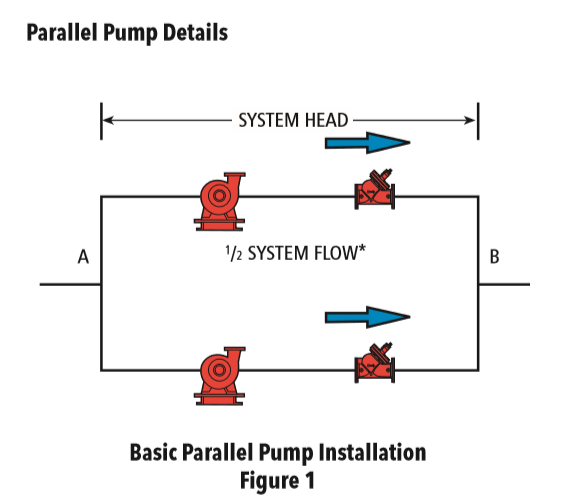
In part 2 of the series I introduced a parallel pump curve.
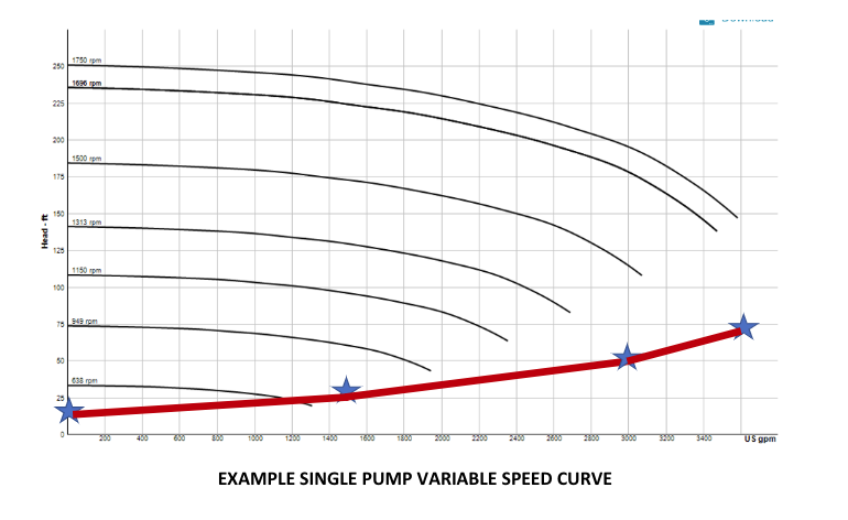
The selection allowed the single constant speed pump to operate on its published curve when operating one pump. This point is the “red” star shown above.
This was and remains the limitation of constant speed parallel pumping unless automatic flow limiting valves are used at the pump discharge. An example of this can be found in a previous MMM.
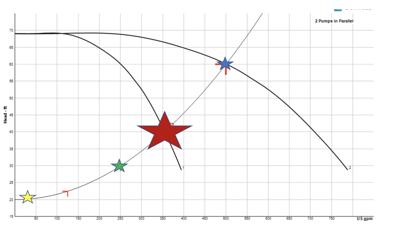
What do we do when the best selection results in a staging point which is not on the pump curve? Let’s look at an example.
Just to mix it up I selected a larger system. This is a chilled water system with a total of 7500 GPM at 200 feet. I selected (3) Bell & Gossett e-HSC pumps in parallel. Notice the 2-pump operation curve. Before the third pump is turned on, the pumping system will be able to provide over 85% of the design flow rate. Two pumps operating will give just under 6600 GPM
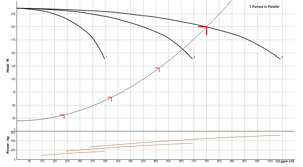
The “traditional” issue would be the lack of intersection of the single operating pump curve and the system curve. The operating point would be well off the curve at the design speed. If we look at this example on a variable speed curve, there are several things to note.
So how do we control the pumps? How can an engineer be comfortable using pumps with the best efficiency and not worry about single pump operation? Let’s look at the options.
End of Curve Concern and Staging Concerns
The traditional methods we may use in constant speed may not apply to variable speed pumping.
We can note that using a Griswold or Bell & Gossett flow limiting valve set at 3400 GPM on the curve above will not work in this variable speed application. It will limit the flow to the curve at 1700 or 1800 RPM but at lower speeds the flow setting of the limiter would be beyond the end of the curve. For example, look at the 1313 RPM curve. The end of curve point is at 2700 GPM at about 80 feet. If the two way valves required 3000 GPM, the 3400 GPM flow limiter would be wide open and no longer controlling. Meanwhile, the 3000 GPM point if off the end of the curve.
Another option would be to raise the control curve. We would have to artificially raise the control head to about 80 feet which will waste a lot of energy! It solves the issue of single pump operation but would not be needed when we have two pumps operating. It also creates a significant energy cost increase when two pumps are operating.
We also note that the traditional KW limits in variable speed drives will only work at the upper speed. The horsepower at some speeds may be the same at multiple flow rates. This means the KW would be similar at multiple points along the same speed curve. This is a recipe for poor performance and cycling of equipment.
Another concern is the staging point itself and how to stage properly. When you stage pumps on or off, there is an instant change in pump head. If the pump head increases, the flow in the system will increase. That increase will result in more flow rate in the system. The increase in flow rate may cause the same pump you turned off to turn right back on. This may happen before the controls have a chance to react and lower the speed to the original head. The same may happen in the staging of a pump on.
Controlling Pumps to Eliminate End of Curve Concern
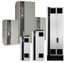
Bell & Gossett has two solutions. First, in a sensored system we simply modify the VFD. The B&G Technologic IPC Variable Speed Drive looks like a simple VFD. It is a VFD. It is a Danfoss VFD, but Bell & Gossett has modified the brains in the drive. They have implanted a pump curve program so this drive along with a flow monitor will continually modify the number of operating pumps to stay on the pump curve. You have the advantage of a quality drive manufacturer coupled with pumps controlled by a company that understands pumps.
You may think the control contractor can do this. It is possible… but you may not like the cost. They would have to program points on the pump curves for every speed and still deal with the staging issues. Using the B&G solution will save time, money, and meetings later.
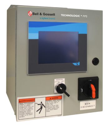
Bell & Gossett’s second solution ties it all together. In a sensorless system we use the VFD above and couple that with a B&G series PPS parallel pump controller. Sensorless variable speed pumping systems can be an option when you don’t want to locate differential pressure sensors and when the system has limited diversity. This controller will stage up to eight pumps in parallel without the use of sensors.
These tools help you to use parallel pumping while selecting the pumps you want to use. No fear of the “old” end of curve issues in variable speed systems. In the last segment of this R. L. Deppmann Monday Morning Minutes we will offer you a specification and detail to make parallel pumping simple to use.
Are you concerned about standby? We will address this in the next R. L. Deppmann Monday Morning Minutes.
HVAC Hydronic Series:
Article 1: What is parallel pumping and why do it?
Article 2: Selecting parallel pumps and the curve
Article 3: Controlling parallel variable speed pumps
Article 4: Parallel pumping and standby capacity
Article 5: Parallel pumping and cost
Article 6: Parallel pumping specifications