In the last R. L. Deppmann Monday Morning Minutes, we presented the cold fill pressure calculation needed for the expansion tank fill pressure. Another piece of information needed is the maximum pressure at the tank. Maximum pressure in expansion or compression tanks in hydronic systems depends on a number of variables.
Maximum Expansion Tank Pressure
The formula shown above is the calculation that the expansion tank programs use to determine the tank size “Vt”. The pressures in the denominator are critical. “Pa” is the PSIA starting pressure in the tank. “Pf” is the PSIA fill pressure. And “Po” is the PSIA maximum pressure. We enter the numbers into the Bell & Gossett ESP-Systemwize selection program in PSIG and the program converts to PSIA.
The following descriptions give you some information to help determine the maximum pressure in the system. We also have a short video on the same subject. You can watch it below.
Pressure Relief Valve Setting and Maximum Pressure
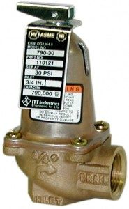
The ASME pressure relief valves we use in hydronic systems are selected based on the BTUH capacity required and the maximum or relief set pressure. These valves start opening at about 10% below the set point. This avoids having them pop open and dumping 20-30-50 gallons per minute of system water. Instead, they crack open and bleed out a little water to try to hold the pressure down. So a 30 PSIG relief valve will start to weep at 27 PSIG. A 100 PSIG relief valve will start to open at 90 PSIG. The maximum pressure the engineer would want at a 30 PSIG valve is actually 27 PSIG, not 30!
Relief Valve Location Compared to the Expansion or Compression Tank Location
When determining the maximum pressure at the tank, the designer should identify the location of the tank in relation to the pressure relief valve and adjust for elevation and pump head. Let’s look at two examples.
Example 1: The conditions for our Part 1 Quiz specified that the first-floor mechanical equipment room has two existing 2 million BTUH boilers with 30 PSIG pressure relief valves. Your design will have a 40° delta T with 180° supply temp. Last week, Expansion and Compression Tanks in Hydronic Systems (Part 2) determined the fill pressure to be 20 PSIG.
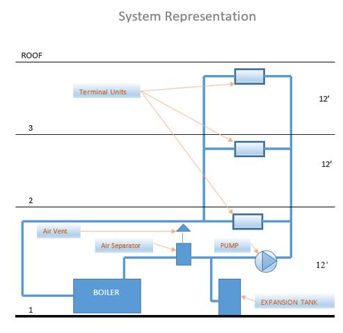
Since the boilers have 30 PSIG pressure relief valves, the maximum pressure at the valves should be designed for 27 PSIG. If we assume no flow between the pumps and boiler, the only difference would be the elevation difference from the relief valve to the tank. This would allow the tank pressure to be slightly higher. We don’t know the elevation difference, so, to be safe, we will just call the maximum pressure at the tank 27 PSIG which is the answer we had for Question 2 of the Expansion Tank Sizing Quiz.
Any answer, 27 PSIG or less but over the fill pressure of 20 PSIG would be correct, but I have a word of caution. As the maximum pressure and fill pressure get closer to each other, the allowable pressure increases at the tank decreases, and the tank gets bigger and bigger.
Example 2: Let’s look at a primary-secondary boiler system. The location of the primary or boiler pump will make a difference in the maximum tank pressure.
What is the Weakest Link in the Hydronic System?
It is always good to verify the maximum pressure in light of the weakest link in the system. Let’s look at the example above and our Question 6 of the Expansion Tank Sizing Quiz. Under Alt 1, we are going to replace the boiler with 2 AERCO condensing boilers. The boilers now have a 75# relief valve setting. The minimum pressure rating of any component in the system is 125 PSIG. What maximum pressure would you use for the tank sizing?
The simple answer would be 75 PSIG less 10% is 67.5 PSIG at the relief valve. Since the tank and relief valve is at about the same elevation, we would round down to 67 PSIG as the maximum. Any pressure below that but above 20 PSIG is acceptable. Why would we go below 67 PSIG as the maximum pressure at the tank?
In the Introduction of the Expansion Tank Sizing Quiz we gave the pump information. The new pumps will have a capacity of 200 GPM at 85 feet of head. The system is variable speed. The pump shutoff head is 95 feet. What does the pump discharge pressure look like? The worst case for pump operation would be if the pump was operating at full speed and at shutoff. 95 feet is 41 PSIG. If the tank is at 67 PSIG and the pump is doing 41 PSIG, the pump discharge would be 67 + 41 = 108 PSIG. This is below the maximum stated pressure of the weakest link at 125 PSIG, so all is well.
Maybe we are concerned about running such a high pressure. Maybe we want to limit it. If the tank maximum was 50 PSIG, the tank would be larger but the pump discharge pressure would be limited to 50+41 = 91 PSIG. Both are acceptable.
What would happen if the fin tube radiation in the existing system had low-pressure expansion compensators?
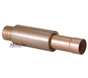
The Metraflex HPFF2 compensator shown above has a maximum pressure of 150 PSIG. Did you know that there are low-pressure compensators which are less expensive but they come with a maximum working pressure of 75 PSIG?
If the maximum pressure of an existing device was 75 PSIG near the discharge of the pump, the maximum tank pressure we would want would be 75 minus 41 or 34 PSIG.
This exercise of checking the weakest link takes a little time but will keep you out of trouble. Remember, just because you can have high pressure does not mean you have to design for that high of a pressure. These decisions are yours based on the maximum tank pressure you design.
Now that you know how to determine the maximum pressure, the next R. L. Deppmann Monday Morning Minute will look at design temperatures and the type of liquid in the system.


