This week our R. L. Deppmann Monday Morning Minute article answers a question about acceptance volume vs. usable volume in a hydro-pneumatic expansion tank.
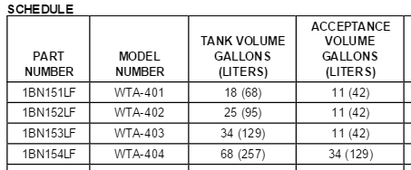
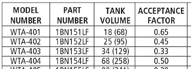
I recently received the following question from Ken in Cleveland, Ohio: “(A recent) Monday Morning Minute article…has an example selecting a B&G Model WTA-404. The submittal sheet shows 34 gallons of acceptance. The literature shows an acceptance ‘factor’ of 0.5. Your example says I only get 3 gallons of storage. Why all the different numbers and why can’t I expect 34 gallons of storage?”
Understanding Acceptance Volume and Tank Volume
This is a question we get often. Let’s start with some important terms.
- Tank Volume: This is the total volume of the tank including air and water
- Acceptance Volume: This is the maximum amount of water volume of the tank
- Acceptance Factor: Sometimes rather than show the acceptance volume, the literature will show a multiplier against tank volume to arrive at the acceptance volume.
- Drawdown Volume: This is the volume of water which leaves the tank from a starting tank pressure down to the minimum pressure
The acceptance volume of a tank is the maximum water volume that the tank can hold if it starts with 0PSIG on the air side (theoretically) and ends with the air side compressed to the maximum pressure that the tank could stand (theoretically). In plumbing systems, we can’t start at maximum pressures and we can’t allow pressures to drop to zero, so there are limits. We charge the tank air side to the minimum pressure we need in the system and then allow water to fill the tank until we reach the maximum pressure we require in the plumbing system.
As the pressure drops in the plumbing system due to use, water leaves the tank and the pressure drops until the tank is empty and the air pressure in the tank is at its minimum. The minimum and final pressures are needed to determine the factor or multiplier we use to find the percentage of tank volume that can be drawn out and used in the plumbing system.
Hydro-pneumatic Tank in a Plumbing System
Here’s a simple illustration of a hydro-pneumatic tank in a plumbing system. In the example we used in the last MMM, there’s a required drawdown volume of 3 gallons. If the tank air side pressure is too low, there will be less storage in the tank. If the air side pressure is too high, no water will enter the tank since the air pressure is greater than the water pressure at the discharge of the pump.
Determining Drawdown
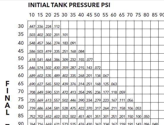
The drawdown is determined by finding the drawdown multiplier. You can use a chart on page 36 of the B&G TEH 1096A manual or download the B&G tank selection program ESP-Tanks.
In our example from last week, we had a maximum pressure of 83 PSIG and a minimum pressure of 78 PSIG. This gives a chart multiplier of about 0.05. The tank volume was 68 so 68 x.05 = 3.4 gallons. The program gives the exact numbers. By the way, if the tank volume times this factor gives you a number greater than the acceptance volume of the tank, you need to select a larger tank. The engineer should include the drawdown volume required and the tank minimum pressure and maximum pressure on the schedule.
A good understanding of these terms will always result in the best tank selection and solution for your client.


