Printer Friendly (PDF)
In last week’s RLD Monday Morning Minute, I described a brief history of pressure-boosting systems and the introduction of the pre-pressurized tank. This week we continue with the sizing of these tanks for constant-speed systems. All of this is to introduce the terms and data needed for the sizing of bladder tanks in variable speed booster systems. Let’s get started….
Sizing Bladder Storage Tanks
Bladder storage tanks are used in constant-speed pressure-booster systems for three purposes:
- Energy savings
- Prevention of short cycling
- Providing a minimum pressure required in the building when the pump is off
Gil Carlson, Director of Engineering at Bell and Gossett, used to say, “No pump uses less energy than a pump that is off.” The more water we can store and use in the bladder tank, the more energy we save. We want to keep the booster off for 15–30 minutes or more in a constant-speed system. Even a small 7–1/2 HP lead pump could use over $400 a year at low or no flow.
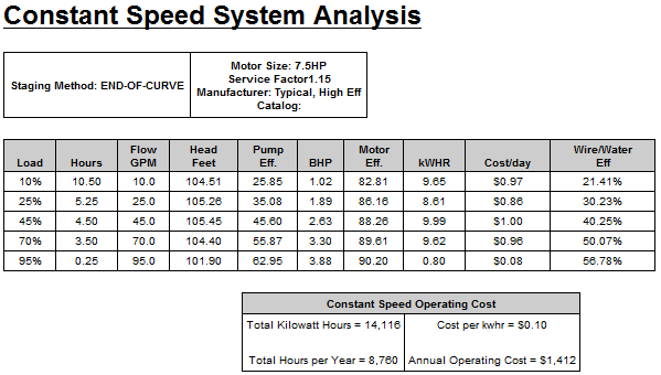
Taken from B&G ESP-PLUS Program
Once we turn the pump off, we want it off for a while. Starter and motor people used to regularly speak about damage caused by starting and stopping a motor too frequently. The industry determined that the standard was to keep the motor starts to under 6 starts per hour, or once every 10 minutes. Now the goal is to store enough usable water in the tank at low flow periods to keep the booster off for 10 minutes.
The third purpose of the tank is to maintain the minimum pressure in a system when the booster system is off. If the tank is located at the pressure booster discharge, the tank fill pressure should be this minimum pressure. This is the pressure needed to lift the water and provide the minimum pressure needed at a fixture without safety factors. The maximum pressure is the booster discharge pressure, in a constant speed system.
Tank Example
Let’s use a tank example, and let’s assume the tank is on the discharge header of the booster system. There may be a better place for the tank but let’s save that for another day. When sizing this bladder tank for hydropneumatic use, you need the acceptance volume required, the initial pressure, and the maximum or final pressure. When the tank is empty it should be charged on the air side to the minimum pressure needed in the system. As the booster system starts, it will fill the tank until the pressure in the tank is the same as the pump. The amount of water in the tank is the acceptance volume.
So let’s assume the discharge pressure of this example constant-speed booster is 80 PSIG and the minimum required is 70 PSIG. This is an apartment building with 150 GPM load. The Bell and Gossett Pressure Booster TEH–1096A design manual shows the recommended acceptance volume for various buildings for 30 minutes of storage.
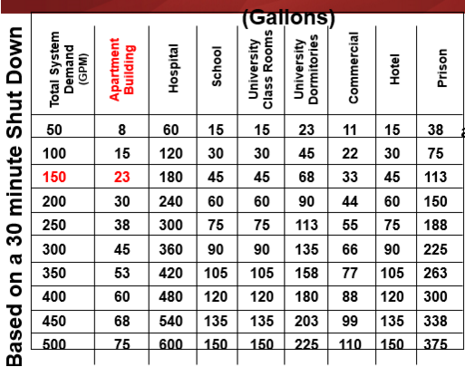
B&G Pressure Booster design manual (pg. 34)
Let’s run some programs. Just as we do in HVAC hydronic systems, we must select a tank that meets both the tank volume and acceptance volume. Let’s select the ASME tank. (For dimensions, go to our plumbing products page and click on the WTA link.)
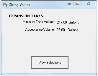
Required acceptance is 23 and tank is 218 gallons
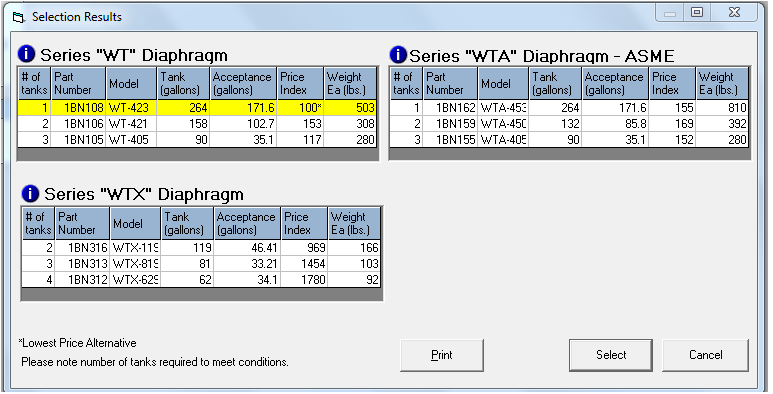
Selections that satisfy both acceptance and tank volume
So what is different in a variable speed system? LOTS…. See you next week.