Back in the old days of building automation systems, most things were controlled using compressed air. This method was called pneumatics and it consisted of a system with an air compressor with small tubing piped throughout the building using low-pressure air in the 3-15 PSI range. The control system could either turn the air to a device on, off, or vary the air pressure to a device depending on the load. These small tubes would control valves, dampers, and pumps among other things in the system. The varying of the signal with the load is what we will refer to as a modulating analog signal.
The Positive and Negatives of Each Analog Control Signal Type
Since the heyday of pneumatics, electronic controls have become less expensive and more mainstream. Today almost everything is electronically controlled in a building automation system. The modulating analog signals are now either a varying voltage of 0-10 volts DC or a varying current of 4-20 milliamps DC. Let us look at the positives and negatives of each type of these analog signals.
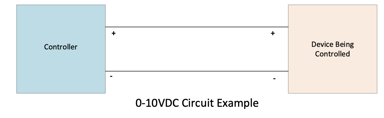
0-10 VDC Signal
Starting with the 0-10 VDC signal being very common in the HVAC industry and most building management controllers and equipment can send and receive a 0-10 VDC signal. This signal is susceptible to electrical interference from motors and other electrical power lines and equipment in the building. Cable length also plays a role in the signal. Longer cable runs can effectively reduce the voltage of the signal due to the resistance of the wire length. Longer cable runs equal more voltage drop in the signal.
Troubleshooting 0-10VDC can be easy using a DC voltmeter and putting the meter leads on the terminals where the wires are terminated. If the meter is reading zero volts, it does not mean the controller is not outputting voltage, it could mean that there is a break in the wire. You must go to the other end of the wire and measure the voltage again to determine if the wire is broken.
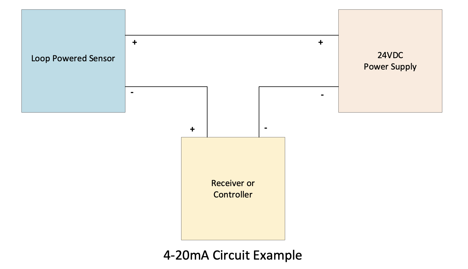
4-20mA Signal
The 4-20mA signal is a better choice for long cable lengths and is also less susceptible to external interference from motors and other electrical power lines and equipment in the building. The 4-20mA signal has been used in industrial process control for these specific reasons.
Troubleshooting is also easy using a DC ammeter. To use a DC ammeter, you first must break the current circuit by removing one of the wires from the termination point and put on of your meter leads in on the termination point and the other meter lead to the wire removed from the termination point. Being that the “minimum” signal is 4mA, it is easy to determine if a broken wire is in the loop as the meter will read 0mA.
In summary, there are pros and cons for each type of control signal. Both types can easily be measured with a technician’s meter as long as it can read DC voltage DC current in mA. You can use either type in HVAC systems and should be proficient in both methods.