Printer Friendly (PDF)
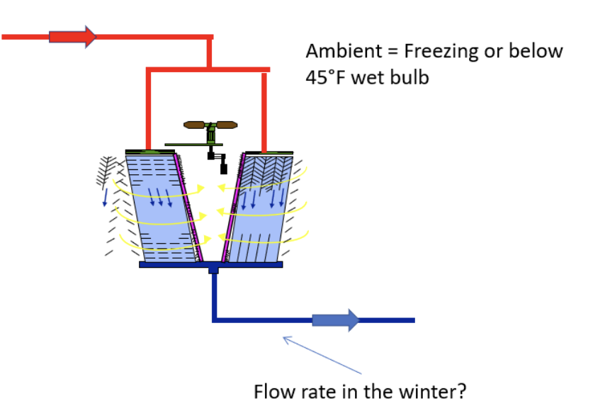 The waterside economizer is normally a gasketed plate heat exchanger. There is chilled water on one side and cooling tower water on the other side of the heat exchanger. What flow rate should we have on the tower side of the water economizer heat exchanger?
Tower Side Flow Rates
Operating cooling towers with temperatures below freezing is a hard duty for the tower. The water may freeze if it is flowing at too low a rate for the size and type of tower. The manufacturer will have specific minimum flow rate requirements depending on the weather.
Those flow rates may vary even in winter months depending on whether the ambient temperature is below freezing. It may even change depending on the cooling tower outlet temperature and range. It is important to select the tower and tower trim for both summer and winter operation. It is important to listen to the tower manufacturer’s recommendations.
I will use a Tower Tech Inc. cooling tower as an example and to get an important point across. The engineer should verify the minimum flow rate for specific outdoor wet bulb and dry bulb temperatures.
Our example system will have a 3 GPM per ton capacity of 2400 GPM assuming a design of 85°F to 95°F. We will use two towers for this example, but we will address a single tower later. Every tower manufacturer will have specific, and possibly different, minimum flow rates and minimum supply temperatures in very cold weather.
Tower Tech has multiple fans in each tower. I selected two towers with four fans in each tower. The capacity at design is 1200 GPM for each tower with the 10°F range. Each fan will have 300 GPM of water flow at design. Tower Tech, and most other manufacturers, recommends VFD control of the fans to save energy and provide additional protective control during the freezing winter months.
In the spring and the fall seasons in Michigan and Ohio, Tower Tech would allow the water flow rates to 100 GPM per fan. A VFD controlled pumping system coupled with operation of both towers, simultaneously, with VFD operated fans could be a huge energy savings. Of course, the flow to operating condensers and their requirements may make this a complex control strategy. This will save energy but coordination between the tower, pumps, and controls is critical for proper operation.
Winter Operation and Minimum Flow Rates
Now for the winter and freezing temperatures. Tower Tech will allow the flow rate to drop down to 100 GPM per fan all the way down to 25°F. When the air temperature gets below 25°F, the minimum water flow rises to 200 GPM per fan. Both numbers assume the VFD fan control mentioned earlier. This is where the engineer should be careful to understand their client, the owner and operator of the chilled water plant.
Let’s assume, as our example, the winter load is only a quarter or less of the design capacity. The urge to jump down to 100 GPM per fan or 400 GPM for this tower when the outdoor temperature is below 32°F is tempting. There are several concerns for the engineer to address.
-
- The plate heat exchanger must be sized for 200 GPM per fan or 800 GPM assuming the tower operates when the temperature is below 25°F. It is important to keep that velocity high to scour the plates and keep the dirty tower water from clogging the heat exchanger. If we design for 800 GPM and drop to 400 GPM, we may save some pump energy but at the expense of higher maintenance and repair costs.
- We may think of the pump affinity laws and immediately remember the R L Deppmann basic pump classes and Norm stating, “Half of the flow is a quarter of the head and an eighth of the horsepower”. Remember, those rules are specifically for closed systems.
Assume we had two 1200 GPM pumps at 60 feet for our two towers. This way, we have a pump operating if the tower is operating. At 200 GPM per fan or 800 GPM in the dead of winter in water economizer cycle, there will be less pump head required but it will not be a quarter of the head.
If you know me, you know I want to segway into a pump conversation. I’ll save that for a separate article. Just remember, the tower elevation or height will remain constant, and the heat exchanger was designed for high velocity and pressure drop.
If we get greedy and try to drop to 400 GPM instead of 800 GPM, the constant speed pump energy savings would be rather small. A variable speed pumping system would save more energy but also complicates the system control. Now we must deal with point number three.
3. Are we going to take chances on damaging the tower or at best, causing additional maintenance hours because of temperature control dead band, poor sensor location, or sensor error? Is the owner, your client, going to leave the system in completely automatic mode and NEVER manually adjust things? Is the small savings worth the risk? Do you even have a drive or VFD on the tower pump?
Regardless of the tower manufacturer and type of cooling tower you are specifying, there will be choices. I am suggesting you identify the flow rate required for comfortable operation of the tower when the outdoor temperature drops below freezing in the winter and not attempt to squeeze that last drop of energy savings. In our example, that would be 800 GPM if four fans were operating.
Single, Large Tower Operation Thoughts
What happens if there is a single cooling tower, and the winter load is significantly lower than the summer load? The minimum flow rates are still an issue. Assume the single tower in our example would have eight fans. That is reasonable since the parallel operation had two towers with four fans each.
The issue is the load. Our example assumes the winter load is 25% of design. We still need 200 GPM per fan for our example. That would raise the flow rate to 1600 GPM. That will not work without a large heat exchanger, due to the flow rate, and a very small tower temperature range.
In this case we will do something to make the tower look smaller in the winter. Some tower manufacturers will use two inlets and outlets with control valves and operate only half the tower. There are rules to follow if you do this.
Our example manufacturer, Tower Tech, can provide dual inlet openings at opposite sides of the tower. They can also split the tower in two by using a control valve to divide the tower. I’ll address this in a later blog. But this strategy would make the eight-fan tower look like a four fan or three-fan or even a two-fan tower in the winter.
In Conclusion…
In our example, I will say the following. We will assume the 1200 GPM flow rate in the summer for both towers at design and an 800 GPM flow rate in the winter in a single operating tower. We will assume the 800-ton summer load will drop to a quarter of that in the winter. Obviously, both summer and winter loads should be calculated and provided to the tower manufacturer when selecting the best solution.
I also want to caution about operation of the water side economizer and a chiller at the same time. The flow rate mentioned above is for the water side economizer. When a chiller is called into action, the pumps will have to meet the requirements of the heat exchanger and the chiller.
There are also chillers which may operate in cold weather without operation of the condenser. These are referred to by at least one chiller manufacturer as a “free cooling” chiller. There may be flow rate and temperature requirements by that manufacturer.
We will take this example and determine what type of capacity will be available to the water economizer heat exchanger in the next R. L. Deppmann Monday Morning Minutes.
PART 1: Free Cooling Heat Exchangers
PART 2: State Energy Codes
PART 3: Cooling Tower Temperatures
PART 4: Chilled Water Temperatures
PART 5: Heat Exchanger Location