The waterside economizer is normally a gasketed plate heat exchanger. There is chilled water on one side and cooling tower water on the other side of the heat exchanger. What temperatures could we expect the cooling tower to provide to the heat exchanger in a northern winter and still provide cooling capacity?
Let me start by saying this is a great deal of detailed heat transfer jargon for a blog. If you are an engineer in Michigan or Northern Ohio contact R. L. Deppmann and we can help with the engineered design of your waterside economizers and even join you in a brainstorming session. If you are outside of our territory, please contact your Bell & Gossett representative. The engineer will have the understanding to choose the conditions to standardize on which will match the location winter conditions, the cooling tower, the heat exchanger, the pumps, and the controls.
Tower Side Flow Rate Summary
In part 6 of this series, Waterside Economizers Part 6: Tower Side Flow Rate, the minimum flow rate required for the cooling tower was the subject. There may be a minimum flow rate at 45 degrees outdoor air temperature when the ASHRAE 90.1 energy standard requires the water side economizer to be active and able to provide up to 100% of the load. There may also be a higher flow rate required when the outdoor air temperatures are below freezing.
The plate heat exchanger used as the waterside economizer should be sized at the larger of these two flow rates. If we size on a smaller flow rate, the pressure drop through the heat exchanger would increase dramatically when the larger flow rate was required. The cooling tower pump may not be large enough for this added pressure drop. Here is the example used in part 6.
The chilled water side of the water economizer will require a quarter of the 12,000 MBH capacity or 3000 MBH in the winter. The tower side will require two towers for the design capacity and half of a single tower capacity in the winter. The flow rate of a single tower in the summer is 1200 GPM. The minimum flow rate when well below freezing is 800 GPM. The minimum flow rate just below and above freezing is 400 GPM.
What about the tower side temperatures?
Near Freezing Winter Load and the Tower Side Temperature Range
We start with the required heat load of 3,000,000 BTUH. This will give us a cooling tower range for a given GPM.
- 3,000,000 BTUH with an 800 GPM flow rate will have a 7.5°F range.
- 3,000,000 BTUH with a 400 GPM flow rate will have a 15°F range.
The cooling tower supply water temperature has everything to do with the approach of the tower at given outdoor temperatures.
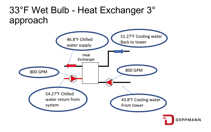
- At 33°F wet bulb, our example cooling water from the tower is at 43.8°F when flowing 800 GPM and based on the BTUH formula, the cooling water back to the tower from the heat exchanger will be 51.27 °F.
- If we specify a 3°F approach between the heat exchanger and the tower supply water. The heat exchanger will be selected to provide a chilled water supply of 43.8 + 3 = 46.8°F. To create a heat load balance, the chilled water return from the system will be 54.27°F.
- What happens if we try to drop to the very minimum flow rate recommended by the Tower manufacturer? In this example, 400 GPM. At 33°F wet bulb, our example tower will provide supply water at 50.9°F when flowing 400 GPM, and based on the BTUH formula, the cooling tower return from the heat exchanger will be 65.9°F. The heat load at the heat exchanger must match on both sides. The chilled water side will end up with an average temperature of 61.4°F which is an elevated temperature to cool with at best and, at worst, may result in numbers that are impossible to hit.
I discussed the flow rate in part 6 of the series. Although the tower may be capable of operating at low flow rates at near-freezing temperatures or lower, the resulting supply temperature and range may not make sense on the chilled water side.
45°F Wet Bulb Winter Load and the Tower Side Temperature Range
We selected a heat exchanger, for our example winter load of 3,000,000 BTUH at a 33°F wet bulb temperature. What happens when we operate the tower and the waterside economizer at the ASHRAE 90.1 starting temperature of 45°F wet bulb?
The supply temperature available from the cooling tower will rise a good amount. The chilled water supply will rise also. Let’s look at our example.
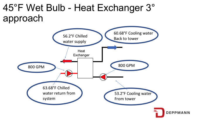
- At 45°F wet bulb, our example tower will provide cooling water from the tower at 53.2°F when flowing 800 GPM and based on the BTUH formula, the cooling water back to the tower from the heat exchanger will be 60.7°F.
We have already selected the cooling tower and the heat exchanger. We can do a performance run on the heat exchanger to see what we will get in this warmer weather. These numbers are going to look high, but they are what they are.
In our example system, using 800 GPM of tower water flow rate, here is what we get.
As the chilled supply water temperature rises, the coil control valve will open more to satisfy the space. The coil will have turbulent flow, but the coil log means temperature difference or LMTD will drop. It will drop quickly at these higher temperatures. The average chilled water temperature here will be 59.1°F. A quick estimated calculation, for this example, shows the coil sensible output will drop to less than 25% of design and the latent output will be 0%. That may be acceptable. It is a quarter of the design summer load of the towers. That said, there is a good chance we may require some mechanical cooling.
Next week is the fourth of July week. We will have some fun facts from our revolutionary forefathers. On July 10th we return with part 8 of this series.
PART 1: Free Cooling Heat Exchangers
PART 2: State Energy Codes
PART 3: Cooling Tower Temperatures
PART 4: Chilled Water Temperatures
PART 5: Heat Exchanger Location
PART 6: Tower Side Flow Rate


