Printer Friendly (PDF)
 The waterside economizer is normally a gasketed plate heat exchanger. The cooling tower water supply temperature to this heat exchanger varies with the weather. The chilled water outlet temperature from this heat exchanger will also vary with the weather. That chilled water variation can cause issues with both chiller control and latent heat. There is a solution, and it is all about where to locate the heat exchanger in the chilled water system.
The Waterside Economizer’s Best Location
In the last R. L. Deppmann Monday Morning Minutes, Water Side Economizers Part 4: Chilled Water Temperatures, we outlined several issues with the chilled water coil output, chilled water reset control, and sensible vs. latent heat issues. Each one of these may or may not be an issue on a project-by-project basis when showing the heat exchanger in parallel with the chillers. In my opinion, there is only one place a waterside economizer should be located.
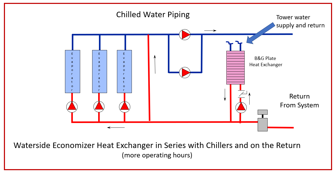
It makes no difference if the system is primary secondary or primary variable, the free cooling or waterside economizer heat exchanger should ALWAYS be located on the chilled water return piping. The system piping shown above has many things going for it. Before we show examples of heat exchanger sizing, we will answer a few questions you may have.
- Why place the heat exchanger on the return?
-
- The heat exchanger will see the coldest supply water from the cooling tower and the warmest chilled water from the system. This will keep the size and the cost of the heat exchanger to a minimum.
- Why is there a one-pipe primary pump from the CHWR to the heat exchanger?
-
- Plate heat exchangers have very small passageways. It is important to keep the velocity high to scour the plates. The chilled water distribution system is variable flow/variable speed. The normal winter velocity in the piping system would be much lower than what the heat exchanger would need.
- ASHRAE 90.1-2013 section 6.5.1.2 states, “water-to-water heat exchangers used as part of a water economizer system shall either have a water-side pressure drop of less than 15 ft of water, or a secondary loop shall be created so that the coil or heat exchanger pressure drop is not seen by the circulating pumps when the system is in the normal cooling (non-economizer) mode. Using the pump allows for higher pressure drops and lower first costs.
- Why is there no standby pump shown on the heat exchanger?
-
- The water economizer is not critical to the operation of the system. I see no need to add the cost of the standby pump in this operation. The heat exchanger and pump may be serviced as a unit. Of course, as a Bell & Gossett pump supplier, we would gladly accept the order for the standby pump. 😊
- Is there an option to eliminate the water economizer chilled water pump?
-
- It saddens me to think of eliminating a pump, but the answer is yes. You could put a two-position three-way valve on the return main. It would be set to be fully open for 100% of the chilled water return to the chillers when the water economizer was not needed. When the economizer is active, a flow meter would adjust the valve to flow the heat exchanger design GPM to the heat exchanger. The assumption here is that the minimum flow of the system matches the heat exchanger flow rate or greater.
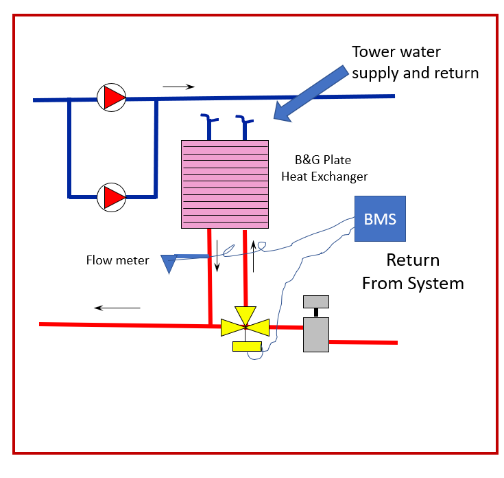
- Just a word of caution. The heat exchanger has a large pressure drop. The controls for the primary distribution pumps would have to adjust the speed so there is enough pump heat for the throttled three way or heat exchanger pressure drop. This complexity makes the single constant speed pump look like a very good choice.
- What happens if the system flow rate is less than the heat exchanger flow rate?
-
- Great question. Unlike the three-way valve solution, this will not be a problem. Water will pull from the chilled water return and the heat exchanger outlet and mix the water going to the heat exchanger. We will look at this with the numbers next week.
- Why is the air separator located before the heat exchanger?
- By locating the air separator where it is shown, it sees the hottest water and lowest pressure. Visit Air Separator Location in Hydronic Systems for more detail. By locating the expansion tank at that same point, all pumps are pumping away from the point of no pressure change in the system.
What About Other Heat Exchanger Locations?
The chilled water return is the only solution I would recommend. Here are some others along with the issues.
No Heat Exchanger System
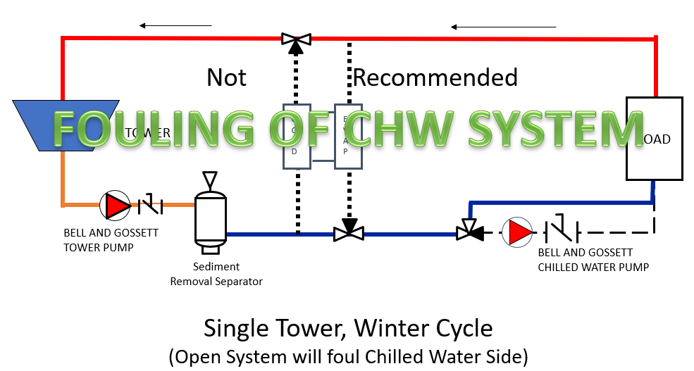
Do not attempt to inject the cold cooling tower water into the chilled water system. Saving the cost of the heat exchanger will have a terrible result.
Parallel Front-Loaded Heat Exchanger
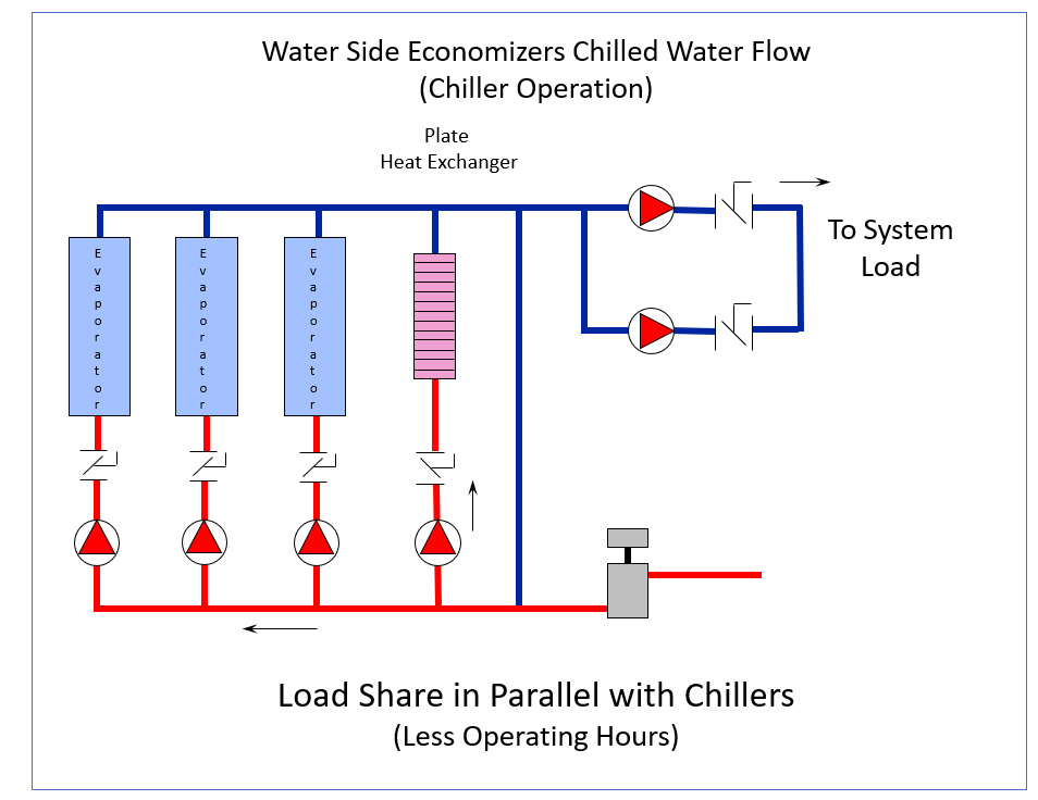
Parallel operation results in mixing the heat exchanger output with the chiller output. This can work but has the issues described in the previous Part 4 blog.
Series Piping but On the Supply
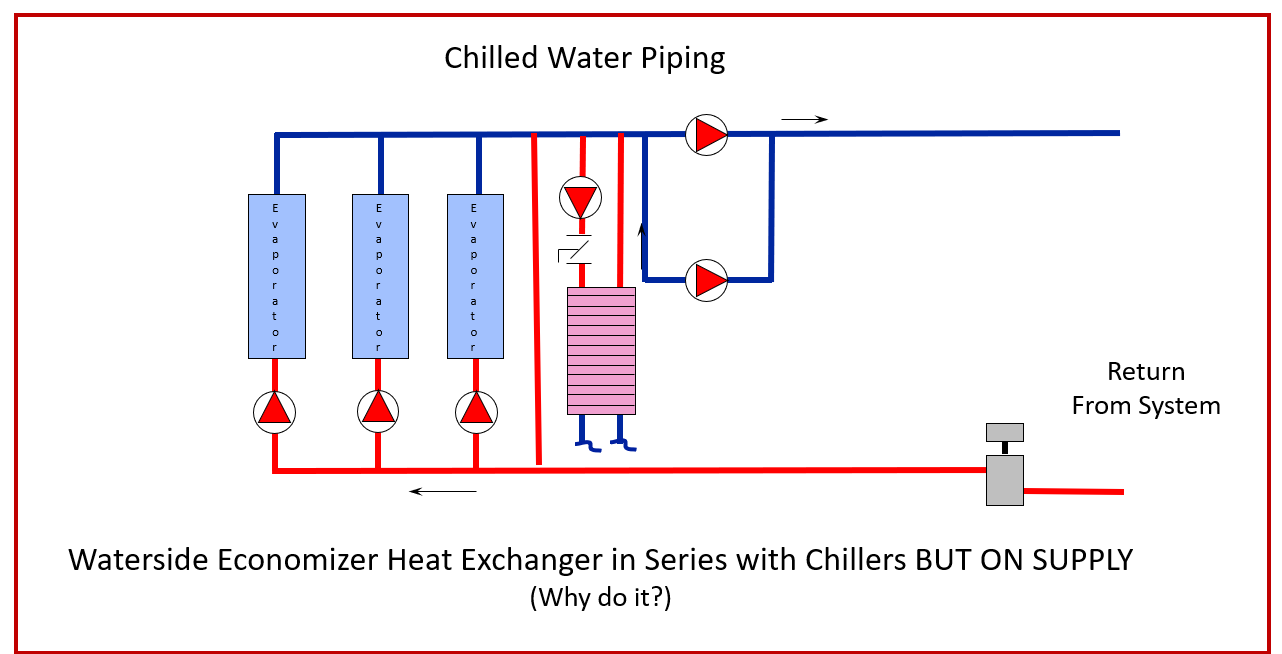
I’ve not seen this one, but it could be possible. It continues to mix the chilled water supply when the chillers are operational along with the water economizer.
Next week we will look at some heat exchanger selections and see how the water economizer heat exchanger located on the chilled water return is a clear winner.
PART 1: Free Cooling Heat Exchangers
PART 2: State Energy Codes
PART 3: Cooling Tower Temperatures
PART 4: Chilled Water Temperatures