Printer Friendly (PDF)
The water side economizer pressure drop is an important point for the engineer to consider. The ASHRAE 90.1-2013 energy standard requires the pressure drop of the heat exchanger be limited to 15 feet if the heat exchanger is served by the system pumps. What does this mean and how does pressure drop affect the exchanger cost?
ASHRAE 90.1 Water Side Economizer Pressure Drop
ASHRAE 90.1-2013 section 6.5.1.2.2 deals with heat exchanger pressure drop. The standard, which is followed by many codes, limited the pressure drop of the heat exchanger to 15 feet. The exception is when the following applies: “secondary loop shall be created so that the coil or heat exchanger pressure drop is not seen by the circulating pumps when the system is in the normal cooling (noneconomizer) mode.”
Circulating Pump Vs. Secondary Loop Pump for the Water Side Economizer: Primary Variable
It is always of key importance to make sure the design team is using the same terminology when discussing the system. The statement above is very clear if the system is a primary variable system. Look at this sketch.
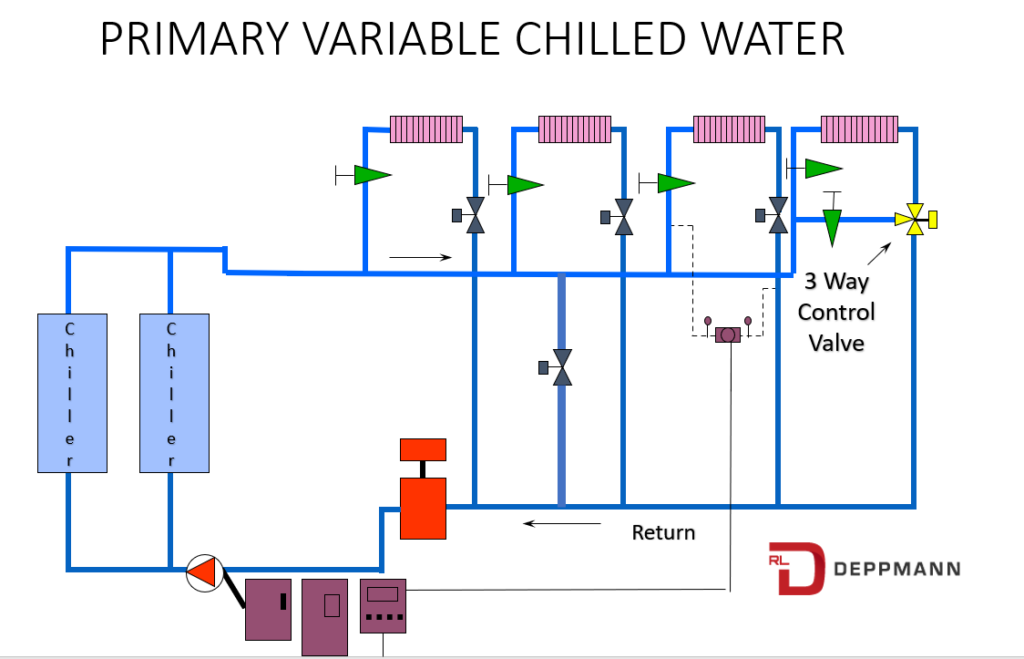
We add the water side economizer or free cooling heat exchanger without an additional pump. There is only one pump or series of parallel pumps and therefore “the pressure drop will be seen by the circulating pumps when the system is in the normal cooling mode”. The term “system” is clear. The pressure drop of the heat exchanger must be limited to 15 feet unless we add a dedicated heat exchanger pump. There will also be a great deal of control concerns which I outlined in the Waterside Economizers Part 5: Heat Exchanger Location Options article.
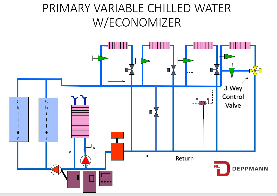
Adding the dedicated heat exchanger pump will allow us to select a greater pressure drop. This may have a positive effect on the initial cost of the heat exchanger.
Circulating Pump Vs. Secondary Loop Pump for the Water Side Economizer: Primary Secondary
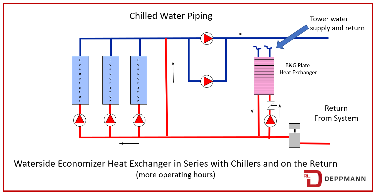
This is a primary secondary chilled water system representation from the article Waterside Economizers Part 5: Heat Exchanger Location Options. The article identifies the heat exchanger location as shown above with its pump or as a separate pumped circuit in parallel with the chillers. In either case, there is a dedicated pump so the pressure drop allowed can exceed 15 feet.
Why is there an advantage to increasing the pressure drop in the heat exchanger? Read on.
Cost Effect of Larger Pressure Drops Through the Water Side Economizer
What can I save by increasing the pressure drop and what does it cost? If we raise the pressure drop through the water side economizer heat exchanger there will be some reduction in the price of the heat exchanger. Here are the numbers for our example heat exchanger which we described in Water Side Economizers Part 8: The Heat Exchanger Approach.
| Heat Exchanger Approach | Example Cost 15 ft. PD | Example Cost 30 ft. PD |
| Example Economizer 3°F Approach | $60,000 | $45,000 |
| Example Economizer 2°F Approach | $70,000 | $60,000 |
I feel like Deja Vu. I remember the old commercials on TV that ended with, “pricing and saving shown is an example and your costs may vary”. The reality is there may be differences based on capacities, lead times, shipping costs, and everyone’s current load. The key is there are savings, and they may not be small.
What will this cost us? There is the cost of the pump and pump installation. Part 5 of this series (link above) mentions that if we do not use the separate pump for the heat exchanger, there is a significant control complication to maintain the chilled water flow rate through the exchanger. If you choose to compare the cost savings above with a system where you are not adding a dedicated water economizer pump and allowing the flow rate to vary in the heat exchanger, the numbers will not be favorable.
If you agree that a dedicated pump is the correct design, then the real costs are the increase in the pump horsepower and the energy used to pump. You will see that there is a clear winner in higher pressure drop if we keep the pump costs relatively the same.
Pump Operating Costs at Higher Pressure Drops.
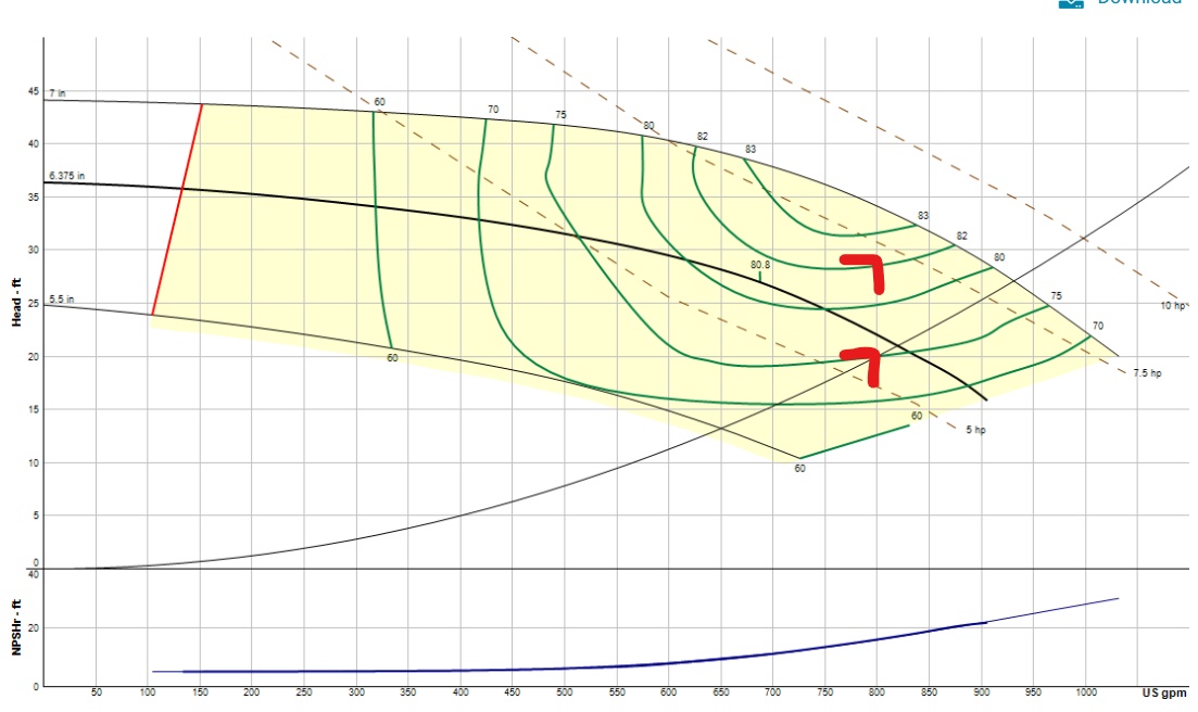
I used our example system and the Bell and Gossett ESP-SystemWize program. I selected a chilled water pump for 800 GPM at 20 feet. This allows 15 feet for the heat exchanger and 5 feet for the small piping.

The lower arrow is that capacity. The pump will be 7-1/2 HP. The upper arrow indicates 800 GPM at 28 feet and uses the same 7-1/2 HP pump with a larger impeller or faster speed if using a VFD. The pump cost would remain the same in either case and the true cost will be the difference in energy being used.
The pump would operate around 90 days per year. It may be on and off at times depending on the weather but we will use the 90 days and 24 hours per day. The additional electrical costs at Michigan rates and 90 days per year would be $300 per year. You can do the math if I save $5000 or $6000 in initial costs.
Contact your B&G representative and have them do the selection iterations. Once you know the costs at 15 feet pressure drop through the heat exchanger, the sales engineer can offer choices for the final decision. Engineering choices are always a good thing. You know your client and you know what is more important to them, CapEx or OpEx.
We have mentioned the concern for higher velocities and the issue of dirt or plugging agents in the water. That will be the subject of the next R. L. Deppmann Monday Morning Minutes.
PART 1: Free Cooling Heat Exchangers
PART 2: State Energy Codes
PART 3: Cooling Tower Temperatures
PART 4: Chilled Water Temperatures
PART 5: Heat Exchanger Location
PART 6: Tower Side Flow Rate
PART 7: Tower Side Temperatures
PART 8: The Heat Exchanger Approach