The gasketed plate heat exchanger and the capacities it should be scheduled at is the subject of today’s blog. The first seven parts of this series were a journey. We presented information on ASHRAE 90.1 and the water side economizer standard. We wrote at length about the winter operation of the cooling tower in cold northern climates. We touched on the load or chilled water side. Here are the key things you need to understand about the equipment.
The Heat Exchanger Approach Temperature
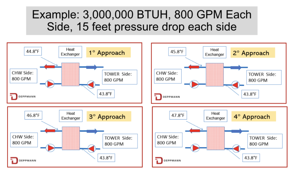
The heat exchanger approach is the temperature difference between the cold cooling tower supply water and the heat exchanger chilled water outlet temperature. You, as the engineer, can schedule any approach that is physically possible but there is a consequence. As these two temperatures get closer to each other, the initial cost and size of the exchanger go up.
Our example system can be used as an example of the effect of heat exchanger approach on the initial cost.
You will notice in the four slides above that the only change is the chilled water outlet temperature. What happens to the initial cost and space required as we change the approach?
The owner will experience the following payment for attempting to get too low a temperature in this economizer cycle.
| Approach | 1 Degree | 2 Degree | 3 Degree | 4 Degree |
| First Cost | 170% | 116% | 100% | 80% |
| Example $$ | $102,000 | $70,000 | $60,000 | $48,000 |
Obviously, the first costs change with location, delivery, specification, optional trim, and other factors. Let’s assume that the three-degree approach solution has a first cost of $60,000. From the table above we can see, in our example system, that if the engineer requests a one-degree approach, the cost will jump to $102,000. A four-degree approach would drop the cost to $48,000. The numbers are a representation of the cost vs. the value. What is the value?
The Real Winter Cost of a Couple of Degrees Approach
The assumption is the operational cost will suffer if we choose to save the owner’s capital cost in the example selections of heat exchangers. Much of this depends on the true load and the weather conditions in the location of your project. The load we selected was 3,000,000 BTUH or a quarter of the full summer load in our Lansing, Michigan example. The operational costs will rise and fall with the load, but we will keep it constant at full load for this discussion.
Look at the Gil Carlson table from the Water Side Economizers Part 4: Chilled Water Temperatures Monday Morning Minutes. If the chilled water supply changes from 44.8°F to 47.8°F at full flow, the sensible deliverable heat reduction will drop to 90%. Since the design winter load is 25%, this is not an issue.
What if the flow rate is not 100%? When the supply temperature to the chilled water coil is constant and the flow drops to 50% of the design flow rate, the sensible heat output will be 85% of design. Visit our blog on flow tolerance at Balancing HVAC Hydronic Systems Part 1: Flow Tolerance for more detail.
The U value, primarily based on velocity, is not an issue. The issue is the log mean temperature difference or LMTD. The coil LMTD will drop with the higher supply temperatures. Even then, the resulting AHU coil output will most times exceed the 25% winter load required.
Spend some time reviewing the numbers for the location of your project. You will find the couple of degrees of approach will be a prudent use of the owner’s money. The cost will be some additional pumping energy, but I think you will find the payback will be over 10 years. This is a complicated subject, and we would welcome an invite to a brainstorming session with our Michigan and Ohio engineering community.
In summary, although a heat exchanger can be designed and built for very low approaches, the engineer may want to consider the first cost of a one- or two-degree approach design. We would suggest a 3°F approach may be a happy median.
PART 1: Free Cooling Heat Exchangers
PART 2: State Energy Codes
PART 3: Cooling Tower Temperatures
PART 4: Chilled Water Temperatures
PART 5: Heat Exchanger Location
PART 6: Tower Side Flow Rate
PART 7: Tower Side Temperatures


