 Today we want to help you in determining the pump head for sump and sewage applications. Simple or not, it is good to review the information required. It is also great when you find a calculator that helps you find and document the answer.
Today’s R. L. Deppmann Company Monday Morning Minutes will give you both. We also are introducing our new plumbing Sump and Sewage website page. Make sure to take a look at this great tool.
Required Pump Head Calculation Information
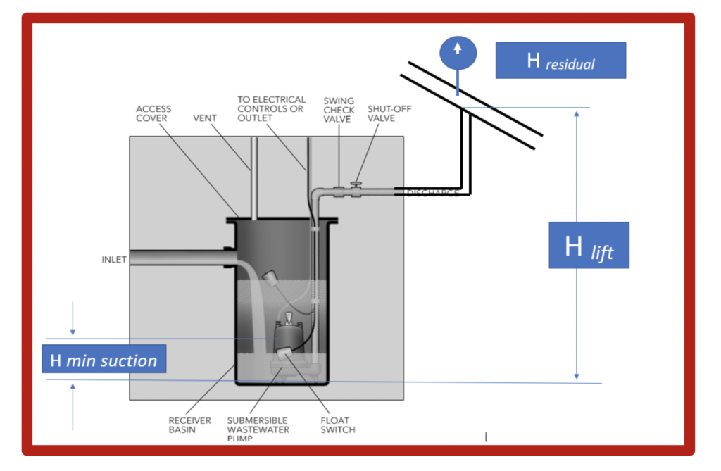
The information required for the sump and sewage pump head calculations are really no different than any other open system. We need the flow rate in gallons per minute (GPM), the elevation or lift required, friction loss, and the pressure of the pipe or system we are discharging into. We assume there is an open basin where the pump is located. The suction pressure is simply the minimum fluid level in the sump.
The calculations will be:
Htotal = Hlift + Hfriction + Hresidual – HDmin suction + Hsafety
Our assumption here is that we are piping into a gravity main. Forced main Grinder Pump applications will require a different calculation and friction loss which are not covered in this blog.
DO NOT USE THIS ARTICLE FOR GRINDER PUMP SIZING
Pump Head Calculation: Residual Head Hresidual
Most sump and sewage applications are pumping from a basin up and into a gravity sewer pipe. Those pipes are normally flowing water by gravity and there is no pressure that this pump would have to overcome. If there is any pressure in that sewer pipe, you would have to add that pressure, in feet of head, to the pump head calculations.
Pump Head Calculation: Elevation Hlift and HDmin suction
This is an open system, so elevation in feet that we must lift the water to get into the return main is important. Don’t forget, in a below ground basin, lift (H lift) is from the bottom of the sump and not from the floor level.
The minimum suction elevation of a pump is important. Bell & Gossett publishes minimum pump off levels for their sump and sewage pumps. It is important to verify the actual requirement of the pump your schedule. We provide a table to use for estimating this Bottom float off level on our website.
Pump Head Calculation: Friction Loss Hfriction
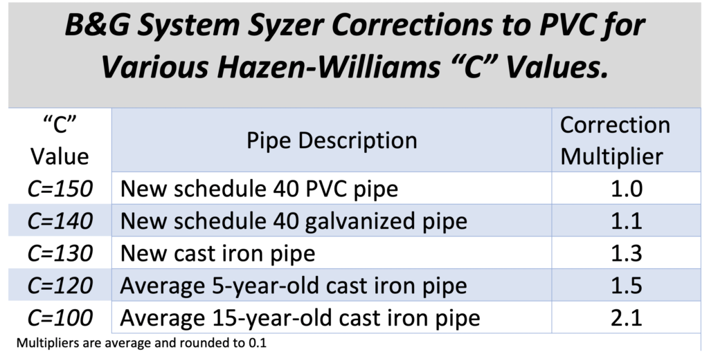
Friction loss in the piping depends on the flow rate, the pipe size, and the roughness of the pipe. Let’s start with the roughness. The Bell & Gossett (B&G) System Syzer calculator is based on new pipe friction loss or C=150. In our last R. L. Deppmann Monday Morning Minutes; Sump and Sewage Pump Design Calculations: Old Pipe or New Pipe in Head Calculations, we discussed the various pipe roughness values.
This friction loss includes the pressure drop through the pipe, valves, and fittings. Bell & Gossett offers a great tool, The B&G System Syzer to assist you in this application. If you wish to use a different value for roughness, this multiplier chart will get you close.
B&G System Syzer Pump Head Calculations
There are two tabs we would use for this application; the Flow/Pressure Frop tab and the Length/Pressure drop tab.
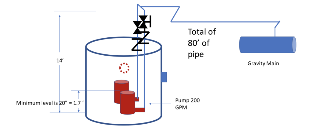
Let’s use the example below and walk through the steps.
- Select Flow/Pressure Drop tab
- In this tab, select pipe materials, pipe size, and enter GPM. Make sure the velocity is above the 2.0 feet/sec scouring minimum. (You can ignore the ASHRAE information since this is not HVAC.)
3. Select the Length/Pressure Drop tab
4. Select the “Help with Total Equivalent Length (T.E.L)”
5. Enter the total pipe length at the top right and enter the number of valves. (Remember if there are two pumps in parallel, we only count the valves for one pump.) Enter the elbows, tees, and other fittings.
6. Read the Total Head Loss on the left. The answer is 7.11 feet
Pump Head Calculation: Safety Factor Head Hsafety
The safety factor can be a total multiplier or additional head. In the example above, let’s make some assumptions. The engineer is a bit nervous about the friction head but confident the elevation is close. Let’s assume they want to double the friction loss which is an extra 7 feet. We can also assume she wants to add a couple of feet to the lift in case the location of the main is not as shown on the as-builts. The safety head is 7 + 2 = 9 feet.
Example Solution
In the formula:
Htotal = Hlift + Hfriction + Hresidual – HDmin suction + Hsafety
We can use the following numbers:
Htotal = 14 + 7.11 + 0 – 1.7 +9 = 28.4 feet
It is a good idea to always check the selected pump for operation based on design flow at the scheduled head and the design flow at the minimum head to make sure there will be no issues with curve runout.
Next week, we will look at the Michigan Elevator Sump Pump Options in the R. L. Deppmann Monday Morning Minutes.


