Wastewater Pumps and Packaged Systems for Building Trades
Sump, Sewage, Effluent, Grinder & Dewatering Pumps
What is the difference? How do I select the right pump?
Water runs downhill naturally. Where it ends up may require a system to collect and pump to where it can flow naturally again. R.L. Deppmann has teamed up with Xylem Bell & Gossett and Gould Water Systems to provide the right solution for your wastewater pumping system.
Which type of pump or package do you need?
Once you know the flow rate and the pump head, how do you decide which pump to select? Is there a packaged solution that includes everything I need?
This webpage will offer a simple step by step procedure for selecting and specifying the right type of pump and components needed to make a complete system. We’ll describe good, better and best solutions and help you make the right decision for your client.
Additional Information
Related Monday Morning Minute: Submersible Pump Application Guide
Sewage Pumps
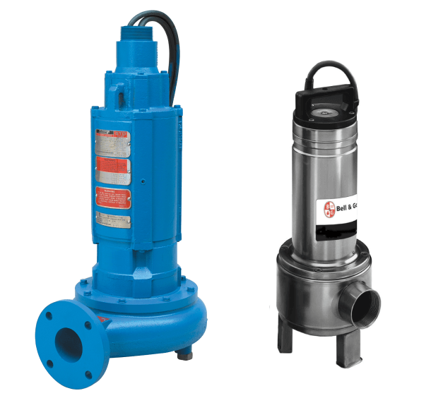
The right sewage pump makes a big difference! This is a place where the commercial and institutional owner want solid performance and long life. Xylem’s Bell & Gossett and Goulds brands offer reliability and provide the building owner peace of mind.
We can help you determine the right pump for your application by looking at the Bell & Gossett sewage pump offering in a Good, Better, Best format. The selection of sewage pumps depends first on impeller type, capacities at best efficiency, benefits, and enclosure required.
Contact us for larger applications. Many pump styles may not be shown on this website.
Non-Clog vs. Vortex Pumps: Flushable Products Don't Always End Up as Pump-able Products!
Non-clog sewage or vortex are impeller descriptions often seen in this industry. What does it mean? Why should I choose one over the other? To help you choose the right pump, you can find answers to these questions and more in our R. L. Deppmann Monday Morning Minute blog.
Non-Clog submersible sewage pumps normally have semi open impellers with large passageways for solids handling. Vortex impellers spin and “pull” the solids through the pump body or volute by creating a sort of “tornado effect” in the pump. Modern waste is different than what pumps saw 30 years ago. Depending on the application, you may want to consider using vortex pumps today.
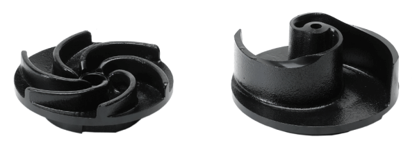
See How a Goulds Submersible Vortex Pump Works
Additional Information
Related Monday Morning Minute: Non-Clog vs. Vortex - What's the Difference?
Sewage and Vortex: Good, Better, Best – What’s the Difference?
The choice of Good, Better, and Best is all about features and benefits vs. the price tag.
Good
- Residential and small office grade
- Lower cost units with either non clog or vortex plastic and iron impellers
- Single carbon ceramic seals
Better
- Commercial and smaller institutional grade
- Medium cost units with either non clog or vortex cast iron or stainless impellers
- Single silicon carbide long life seals
- Class B motor insulation
Best
- Institutional and large commercial grade
- Slightly higher cost with dual silicon carbide seals and optional seal failure alarms
- Non clog or vortex cast iron impellers
- Class F higher rated motor insulation
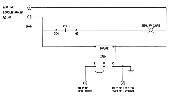
Optional Best Seal Failure Alarm Wiring Diagram.
Capacities: 2" Sewage-Vortex and Non Clog Choices
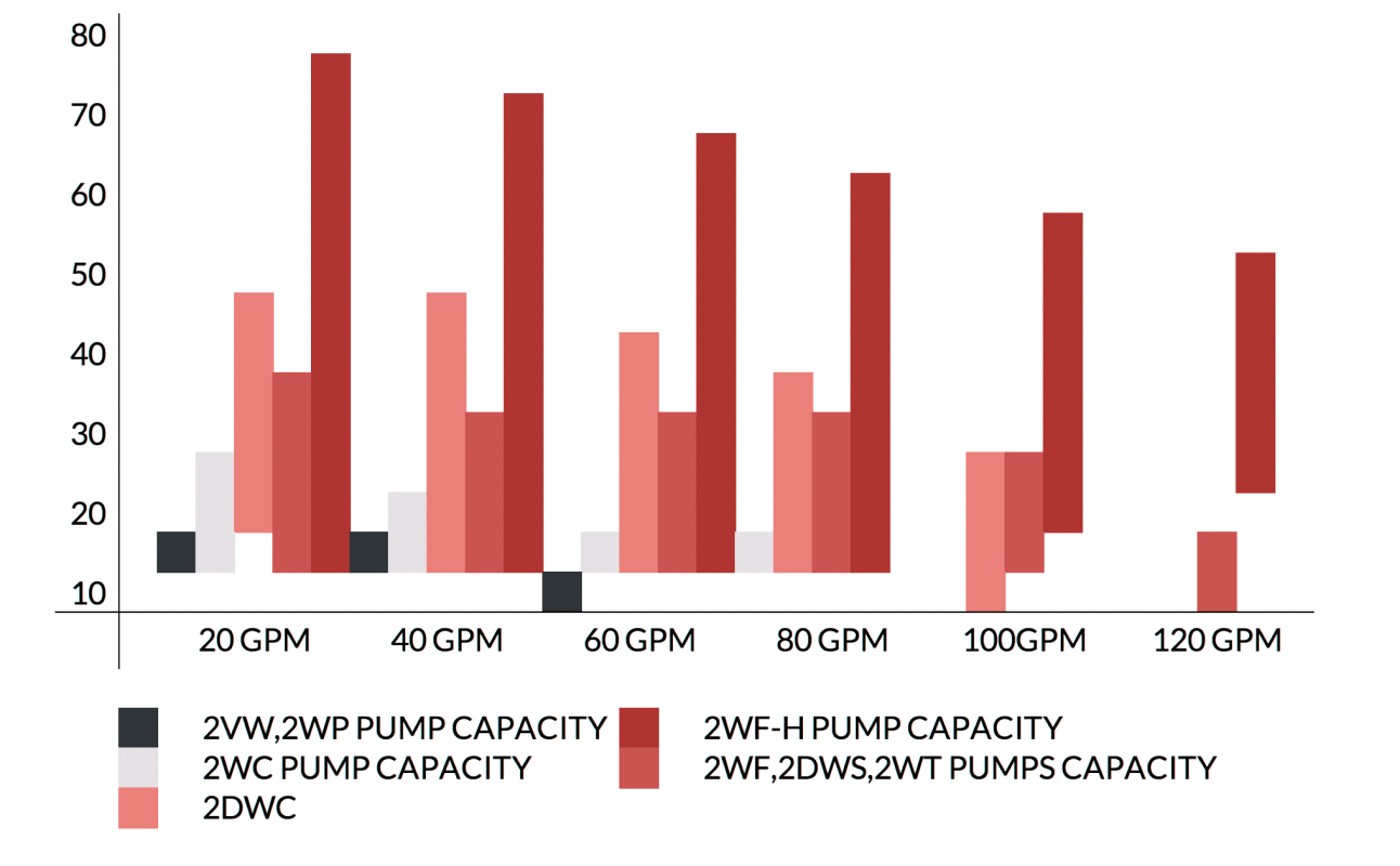
Capacities: 3” & 4” Sewage-Vortex and Non Clog Choices
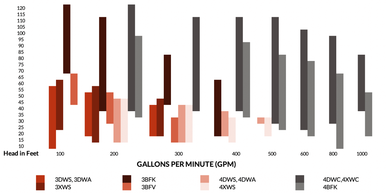
Note: Tables above are approximate and limited by velocity and friction loss
Additional Information
Use ESP-Systemwize by Bell & Gossett for a detailed pump selection, submittal and more
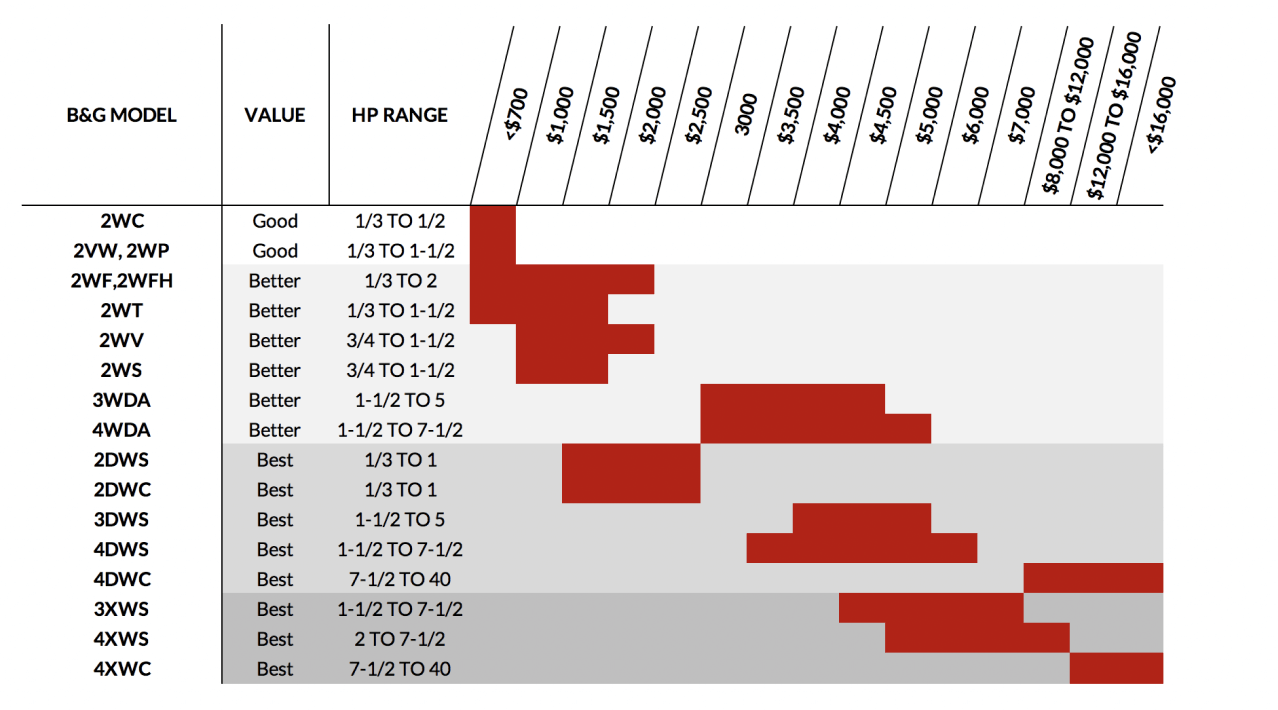
Cost Index: Sewage-Vortex and Non Clog Choices
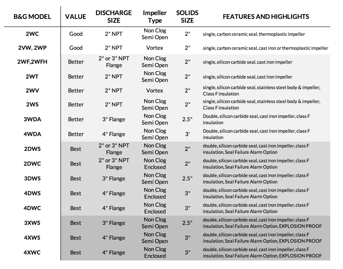
Features: Sewage-Vortex and Non Clog Choices
Check out our Monday Morning Minutes
Helpful tips, delivered to your inbox every Monday.
Sump & Effluent Pumps
Whether the pump is in your home, the bottom of an elevator shaft, or catching storm water in a hospital, pumps that handle water with small solids are called sump or effluent pumps.
The selection starts with your GPM and pump head calculations. Once you have the capacities:
- Determine the Bell & Gossett pump choices for those capacities.
- Reduce the models based on the solid handling requirement.
- Decide whether your client’s needs are served by a Good, Better, or Best pump choice.
What can I find on this page? Good, Better, Best - The differences, the capacities, the cost.
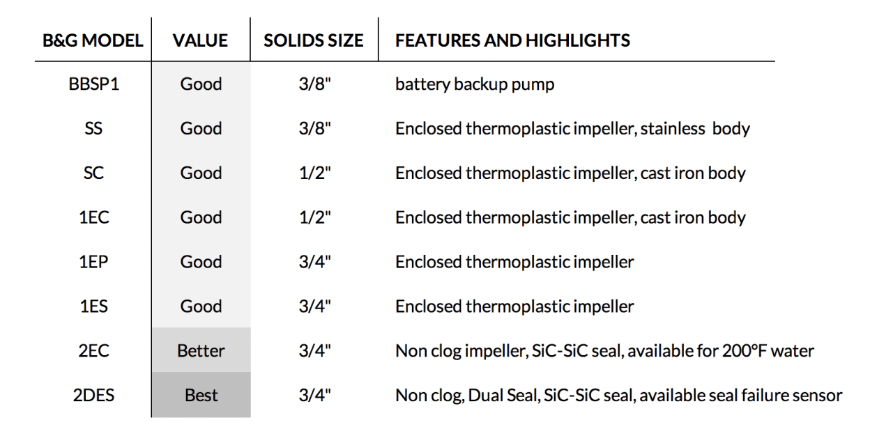
All Bell & Gossett sump/effluent pumps will exceed the low-price models you find in many home centers. Here is what changes a product from being Good to Better or to Best:
Good
- Single carbon ceramic mechanical seals for solids free water
- 1-1/2” discharge size handle solids up to ¾”
- Non-clog semi open impeller style
Better
- Single silicon carbide mechanical seals handle gritty solids better
- High temperature model available
- 2” discharge size handle solids up to ¾”
- Non-clog semi open impeller style with pump out vanes
Best
- Dual combination silicon carbide/ carbon ceramic mechanical seals gives added failure protection
- Optional seal failure sensing probe warns of first seal breach before total failure
- High temperature model available
- 2” discharge size handles solids up to ¾”
- Non-clog semi open impeller style with pump out vanes
Capacities: Good, Better, and Best
Good Bell & Gossett Sump & Effluent Pumps – 1-1/2” Discharge
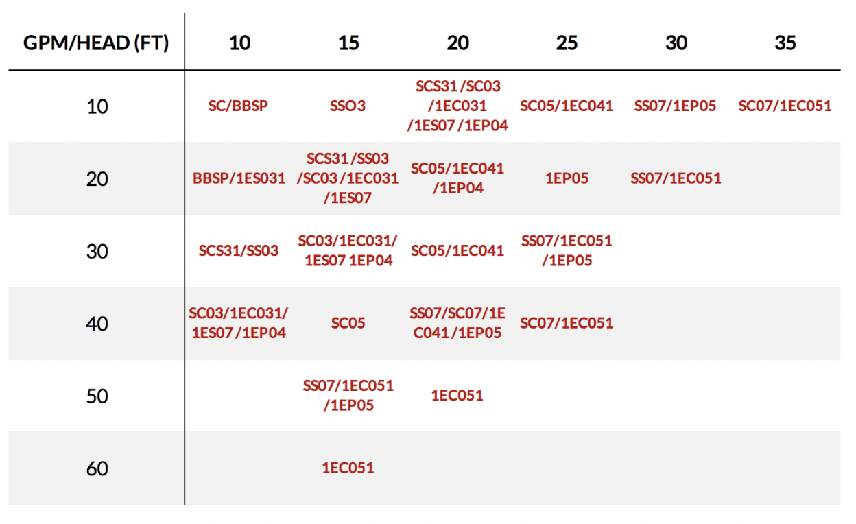
Better & Best Effluent Pumps – 2” Discharge
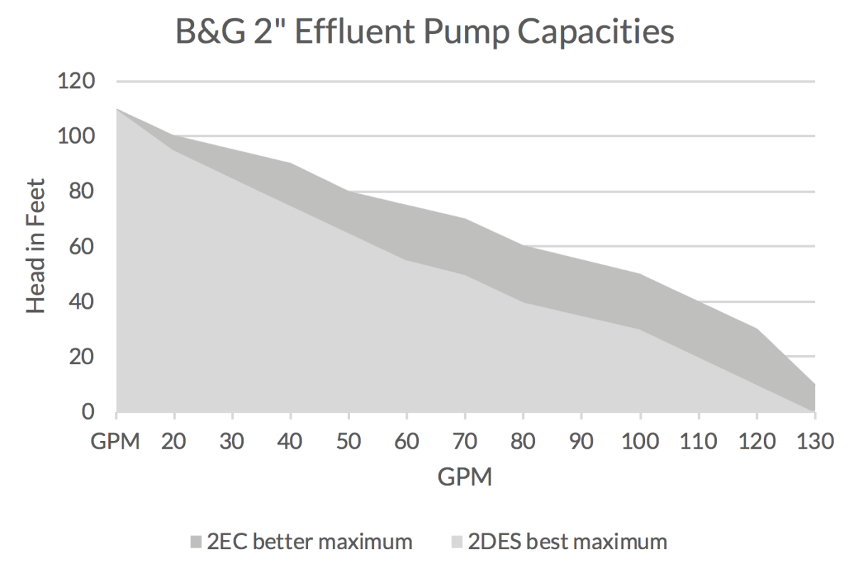
NOTE: For larger capacities we recommend evaluating a sewage pump selection.
Features & Highlights
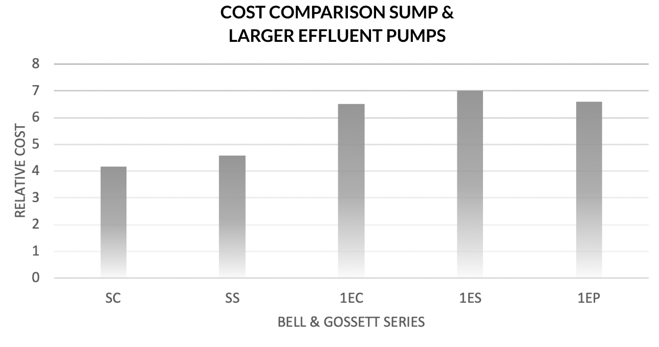
Cost: Good, Better, and Best

Optional Accessories
Can be found in the Basins & Trim section
Additional Information
- Visit the manufacturer's website for sump pumps and for effluent pumps and the BEST Effluent pump
We're Here to Help!
Whether you have a question about the product or want information on product availability and pricing, we've got you covered.
Elevator Sump Pumps
Elevators and disaster movies seem to go hand in hand. Hollywood depicts crowded elevators with water rushing down the sides or filling up from the bottom for intense life or death scenes.
Eliminating water from the bottom of elevator shafts is not just stuff in movies, for plumbing engineers, it is the code and code is about safety.
For information on what is required in your state, read more about the Michigan or Ohio codes using provided links under additional information. Information is also provided to help you learn more about electric elevator solutions, hydraulic elevator solutions for Michigan and Ohio.
Elevator Code and Sump Pumps
Our understanding of the elevator code as of 2019 is that elevators with Firefighters’ Emergency Operation require a drain or sump pump rated at at 3000 GPH (50 GPM) per elevator per ASME A17.1 section 2.2. Based on this, if a pit has two elevators it would require two 50 GPM pumps or a single 100 GPM pump. This multiplication of the 50 GPM rule continues for pits with more than 2 elevators. In Michigan the pump may not be turned off in the presence of oil. The pump must operate whether there is oil or water present. In Ohio, the pump may turn off if there is oil present. The pump will turn back on in the presence of water allowing the oil to float on top of the water.

Additional Information
Michigan:
The State of Michigan Department of Licensing and Regulatory Affairs (LARA) Elevator Division can be reached at elevsafety@michigan.gov and 517-241-9337.
The State of Michigan Department of Licensing and Regulatory Affairs (LARA) Plumbing Division ca be reached at bccplbg@michigan.gov and 517-241-9330.
Hydraulic Elevators: The December 2019 State of Michigan LARA Trades Connection allows the use of the oil sensing and separation system by See Water Inc. which is the one provided in the R. L. Deppmann series S050-MI and S100-MI elevator sump pump packages for use in hydraulic elevators. Oil/water separators are another choice with hydraulic elevators. These often take up significant space and add additional cost.
Ohio:
The State of Ohio Department of Commerce, Division of Industrial Compliance can be reached at C@com.state.oh.us and 614 644-2223
Plumbing Code: 4101:301.6 indicates "Floor drains, sumps and sump pumps shall be permitted at the base of the shaft, provided that they are indirectly connected to the plumbing system".
Electric Elevator Sump Pumps
Pumps require level control. Optional control panel. No oil sensors.
Options:
- Single phase pumps to 1 HP are available with piggyback float switches and NEMA 3-prong pump grounding plugs. (Lowest installed cost)
- Control panel with contactors available for mounting outside elevator with optional high-water alarm
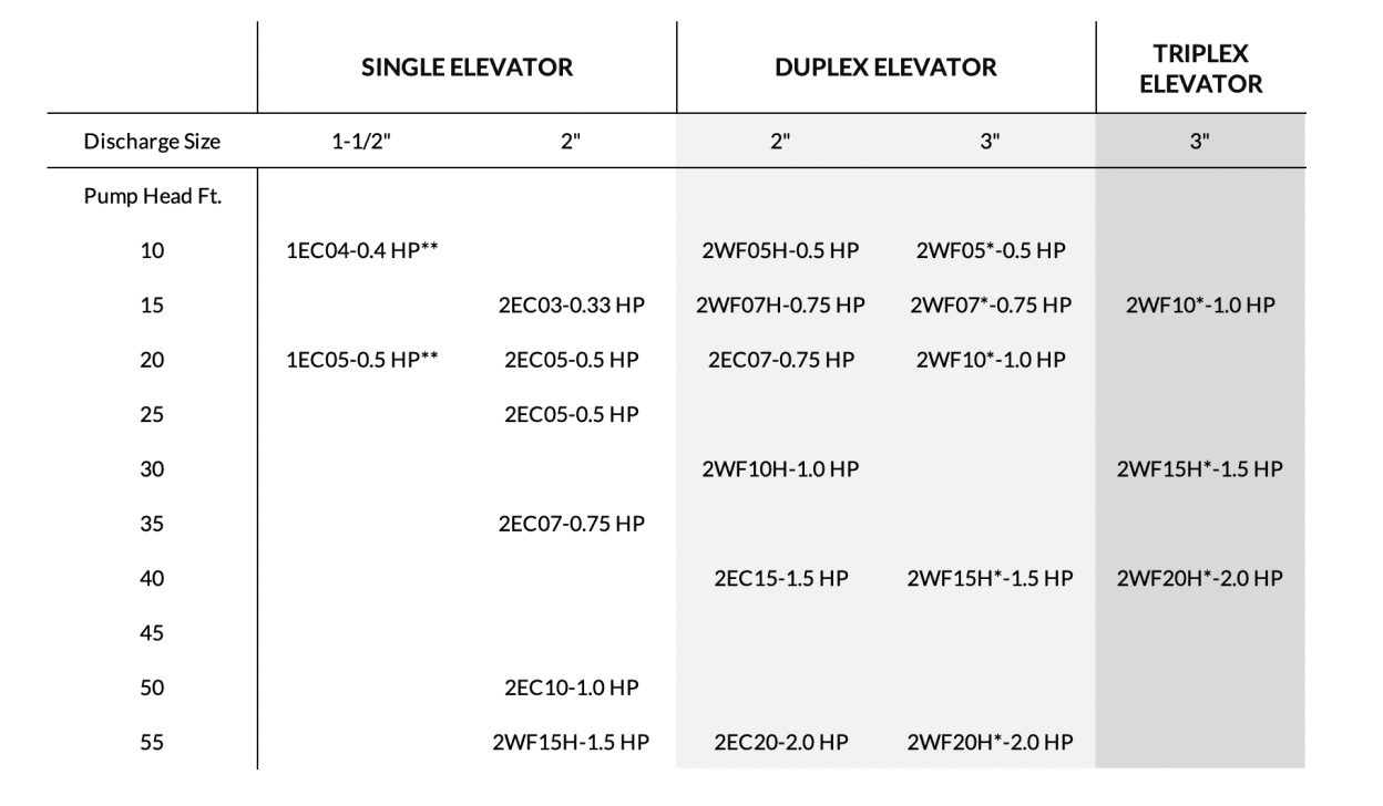
Note 1: Other pumps are available with similar capacities and similar price points
Note 2: Higher pump head models are available. Contact our customer service department at 800-589-6120. Note that higher head pumps may be taller than 24"
* Order with discharge flange A1-3 shipped separately. ** 1-1/2" pumps not to be used with oil present.
Additional Information
More Information, dimensions, and data sheets visit the B&G websites
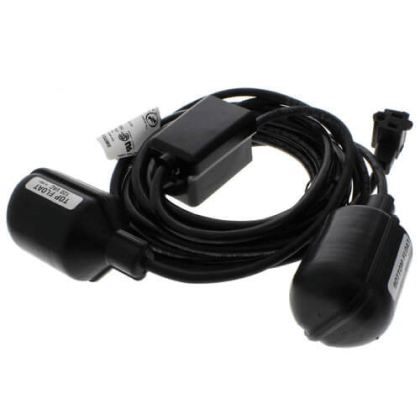
Piggyback option
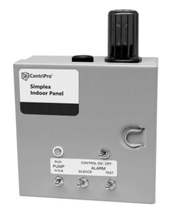
Example electric elevator panel if needed
More information needed on the various choices?
In Michigan and Northern Ohio, you may contact us for a presentation at your office. Visit our Education page for a summary.
Grinder Wastewater Pumps
Think of them as LARGE GARBAGE DISPOSALS! Grinder pumps are used in sewage systems where the municipal system uses a pressurized sewage pipe called a force main..
Why Do Grinder Pumps Have Such a High Head?
Most sewage pumps in buildings are lifting sewage up to a gravity return line. The fluid is mostly water and the total head is simply the elevation or lift plus the friction loss of any pipe, valve & fitting used.
Grinder pumps cut the solids into a slurry. Since the fluid is a slurry and the pipes are normally smaller, it has more friction loss. The pump's high head is the elevation or lift and this higher friction, but it also includes one more component - the pressure in the force main. The force main is under pressure and the pump must overcome that pressure. This is a major factor in sizing the pump head when used for this application.
How do Grinder Pumps Work?
Here is a video from Xylem, the Bell & Gossett parent company, showing the operation and features of a grinder pump. Today’s modern waste poses a problem for many grinder pumps and Xylem has engineered a solution.
Grinder Pumps ---- Good, Better, Best – What’s the Difference?
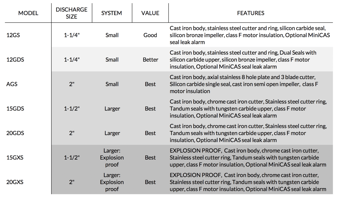
The choice of Good and Better is all about the seal construction. The Good and Better selections are for smaller residential and small commercial systems. Most of the Best selection pumps have larger capacities for larger institutional and commercial systems, and an upgraded seal choice.
Good
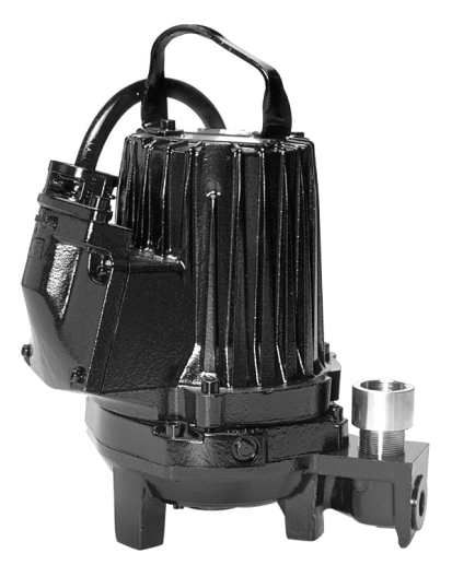
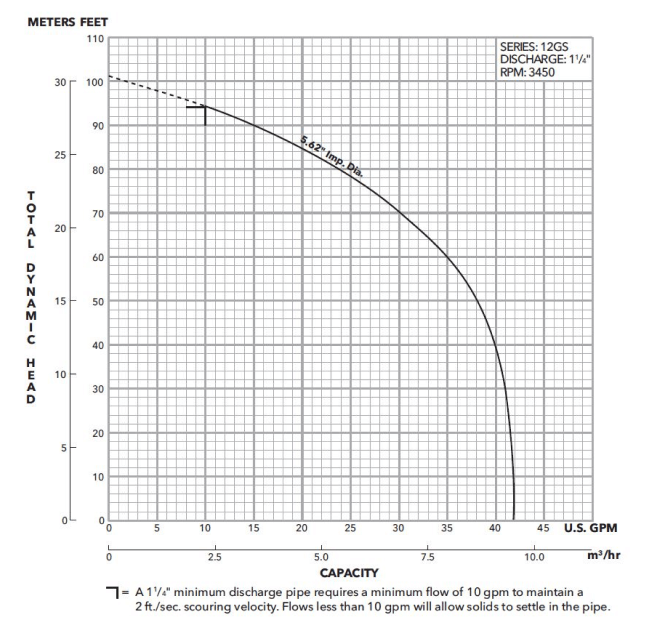
- Model 12 GS: Residential grade
- Lower cost units with a single silicon carbide seal
- Class F Motor insulation
Better
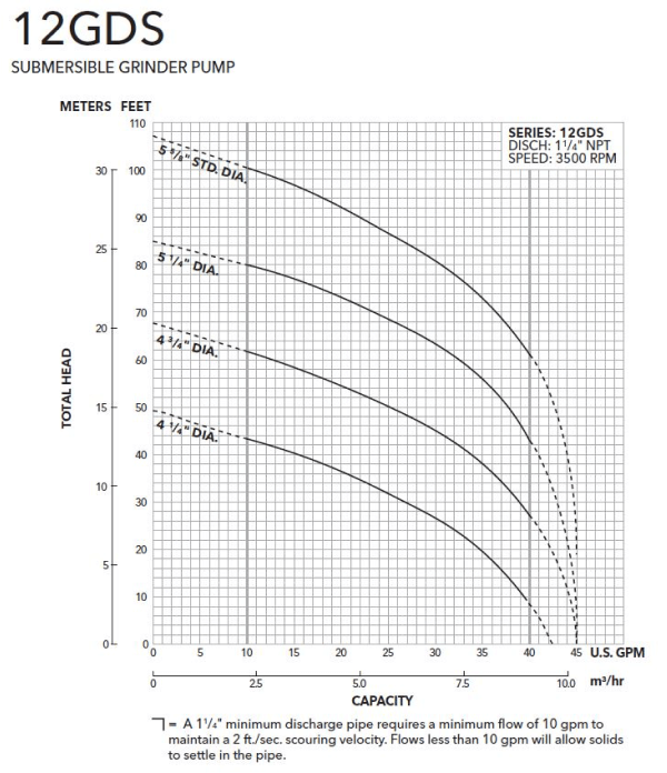
- Model 12 GDS: Commercial and smaller institutional grade
- Medium cost units with dual single silicon carbide long life seals and optional seal failure alarm
- Class F motor insulation
Best
- Model AGS residential and small commercial AXIAL grinder with upgraded cutting design
- Models 15 and 20 GDS: Institutional and large commercial grade
- Slightly higher cost with dual tungsten carbide seals and optional seal failure alarm
- Alarm circuit may be added to existing starter panels or come installed in a new panel
- Class F motor insulation.
Capacities: Good and Better
Capacities: 1-1/2” & 2” Best
Impeller codes B, C, G, H, and L are the 15 GDS; codes A, D, E, F, J, and K are the 20 GDS.
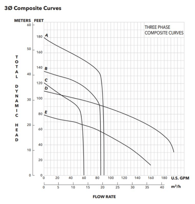

AGS is the best 2" residential and small commercial grinder pump.
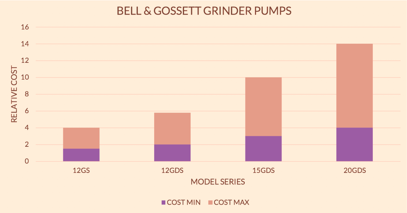
Cost Index: Sewage and Vortex Pumps
Additional Information
More information, dimensions, and data sheets visit the Bell & Gossett websites
Features: Grinder Pumps
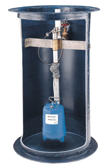
Packaged Grinder Pumping Systems
Take the worry out of missing a component here or there. Avoid searching for that one last part. We offer packaged systems for all the Bell & Gossett wastewater pumps. The grinder pumping package includes many options.
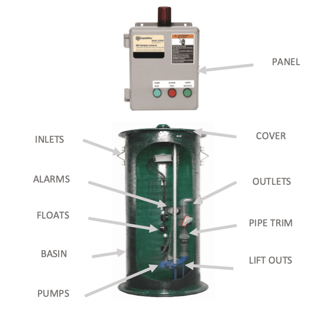
One typical package would have a fiberglass basin with a solid cover, simplex or duplex pumps, guide rail systems for easy removal of the pumps, floats, inlet and electrical grommets check valve, discharge pipe, and a remote NEMA 4 control panel.
For assistance in selecting the right package and options, contact RL Deppmann now.
Request More Information About Grinder Pumps
For specific selection and basin requirements, contact the R.L. Deppmann Company
De-watering Pumps
When water ends up where it should not be, it can be a mess. That is when a great portable pump can make a difference. What makes a great dewatering pump? You have a great pump if you have the correct capacities, if it is a light weight, corrosion resistant construction, and if it's represented by R. L. Deppmann.
Bell & Gossett provides a multitude of pumps which could be used for de-watering applications. Our top choices are featured here:
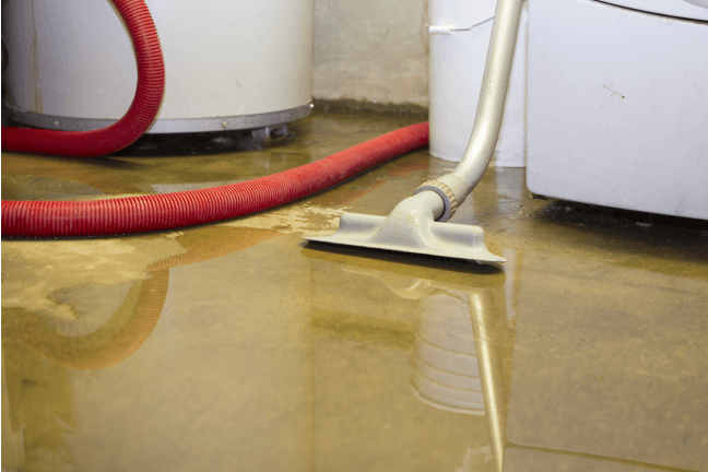
Flooded lower level after pump failure
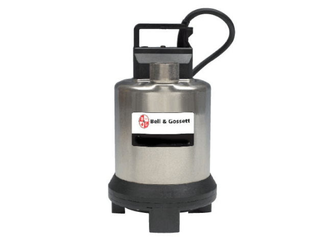
B&G Wastewater Pump - 1ES
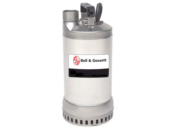
B&G Wastewater Pump - 1DS
Features & Highlights
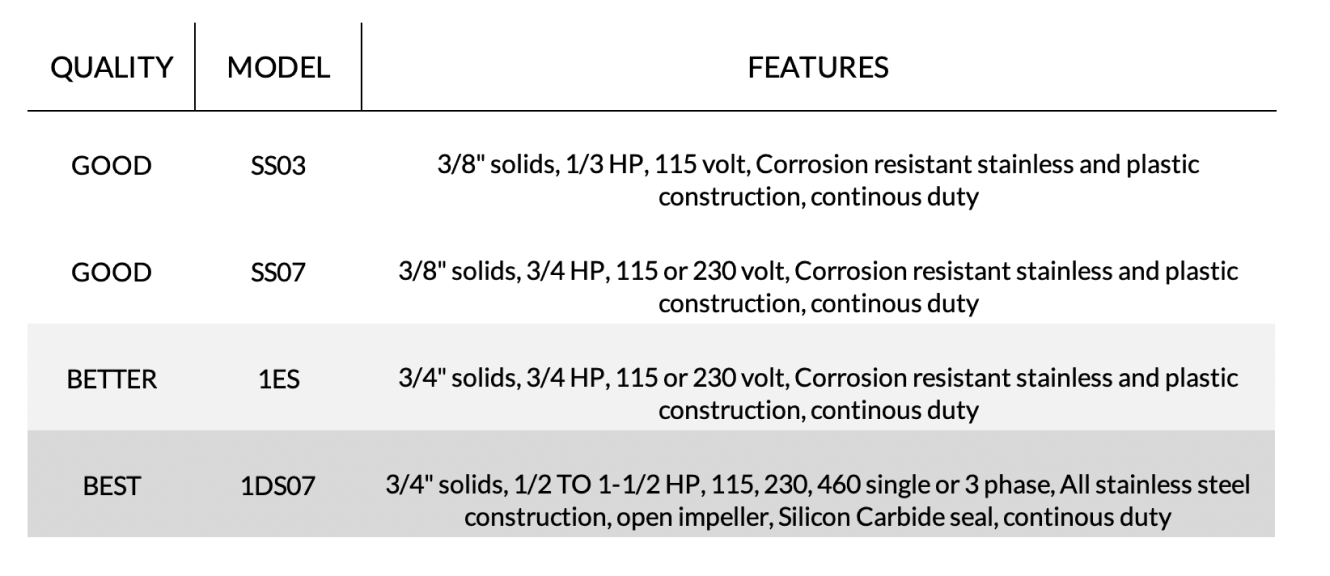
Capacities: Selecting Dewatering Pumps
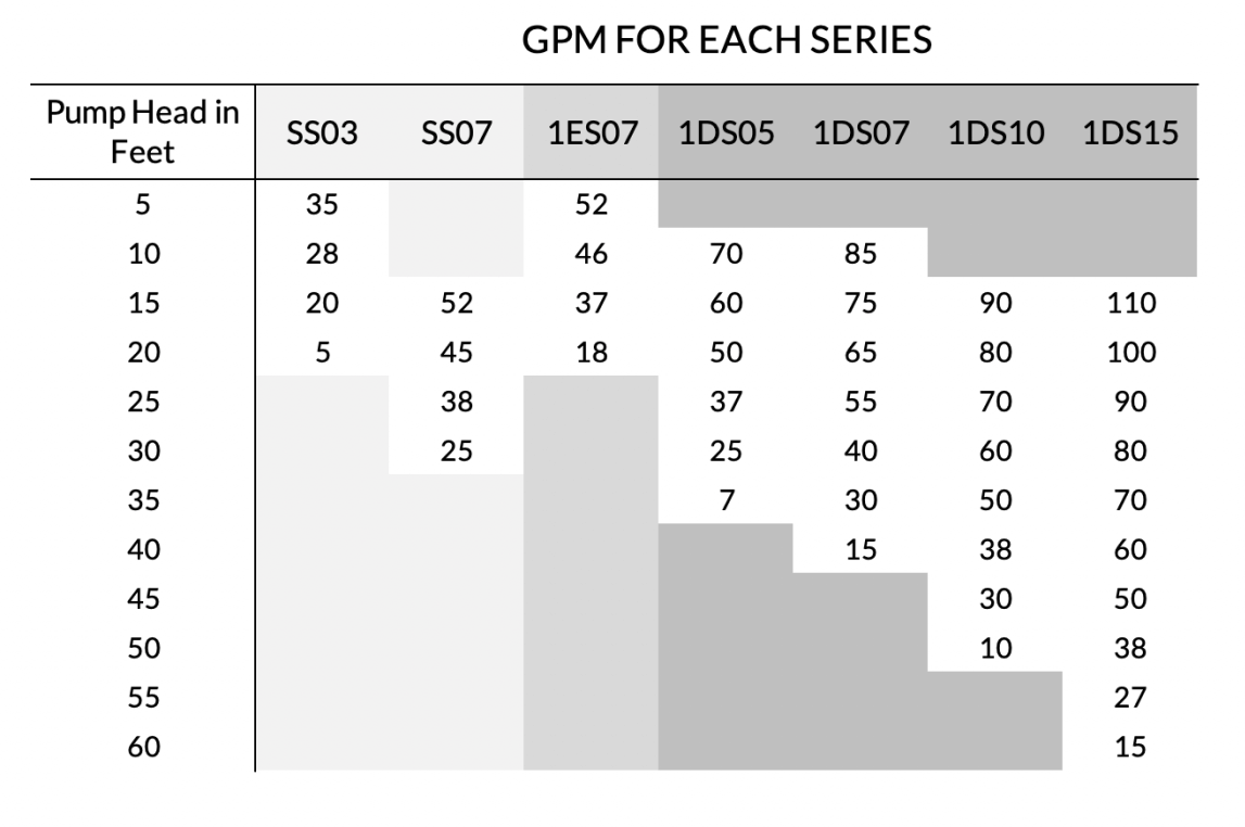
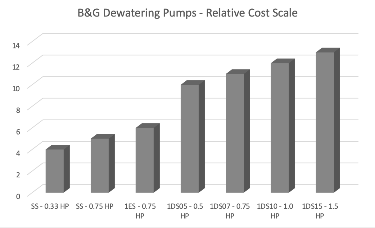
Cost Index: Dewatering Pumps
Check out our Monday Morning Minutes
Helpful tips, delivered to your inbox every Monday.
Basins and Trim
The Pump is just one part of the SYSTEM, You need all the parts….
Let us walk you through the many options you may add to make a sump or sewage system a complete package.
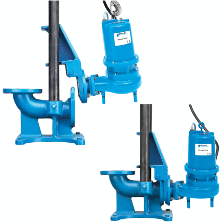
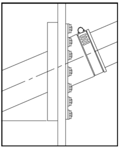
Guide Rail, Base Elbows, Lift Out Systems
Sump and sewage pumping often presents a few installation challenges and even more repair or replacement challenges.
The pump is heavy and dirty. Guide rail systems and base elbows, sometimes called lift out fittings, are the combination of components required to raise and lower the pump down into the pit at installation or service times. These systems are suggested for all but the lightest pumps in small simplex applications.
There is more to a Bell & Gossett package than just the base elbow. Note the A10 models listed below are systems including the base elbow, pump adaptor, bolts, fittings, and upper guide rail positioning bracket. The CBE packages also include all this plus 7 foot and 3 foot chain with shackles.
Additional Information
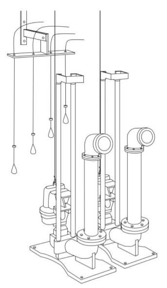
Representation of Duplex Pumps with Guide Rails and Floats
Base Elbow Models for 3” and 4” B&G Pumps
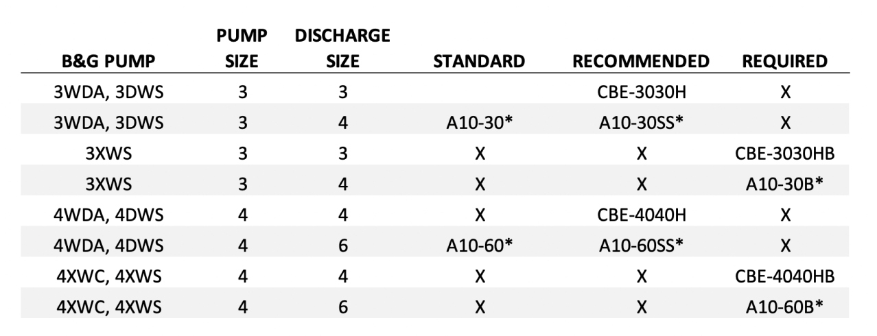
*Requires lifting chains and shackles as separate kit: model (ACHSS10 up to 72" deep sumps, ACHSS20 up to 120" deep sumps)
NOTE 1: 2" guide rails by others. We recommend stainless steel.
NOTE 2: Intermediate guide rails required for pits greater than 11 feet deep.
NOTE 3: If sump is over 72" deep and less than 120" deep you must add chain kit ACHSS20.
Guide Rail Systems 3 and 4
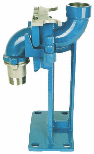
Guide image less rails
Base Elbow Models for 1-1/2” and 2” B&G Pumps
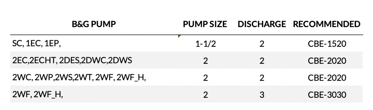
NOTE 1: 1" guide rails by others. We recommend stainless steel.
NOTE 2: Intermediate guide rails required for pits greater than 11 feet deep.
NOTE 3: If sump is over 72" deep and less than 120" deep you must add chain kit ACHSS20
Additional Information
Sumps and Basins
The sump and sewage pump basin may range from a 24” square hole at the bottom of an elevator shaft to a 10-foot concrete rectangle. The purpose is to store fluids from the bottom of the lowest inlet to the minimum submergence of the pump selected.
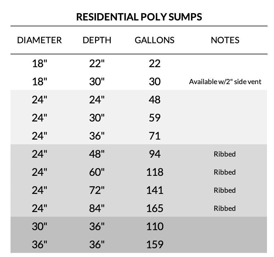
R. L. Deppmann offers polypro residential and fiberglass commercial sump basins for underground installation. The minimum sump basin diameter is dependent on the number of pumps, the use of base elbows, and the allowable depth.
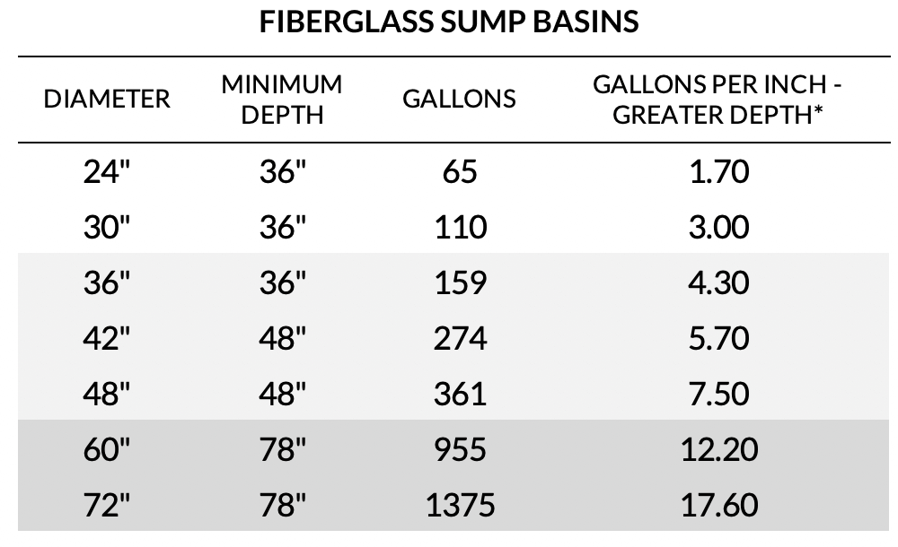
* Approximate gallons per inch. See Manufacturer's literature for exact volume.
NOTES: Covers and inlets ordered separately. B&G or AK brands. We recommend the basin be ordered with the anti-flotation collar. These are built in and available in fiberglass or steel. The anti-flotation collar cannot be added later.
Additional Information
Fiberglass Sump/Basin Trim
Required Mounting Studs:
When using the base elbows and guide rail systems, we strongly recommend you specify and purchase the SMS simplex mounting studs or DMS duple mounting studs. These can be added to the sump for mounting of the bases. If the basin is over 5 foot deep, "a false bottom" or separate plate to mount the base elbows will help with installation.
Recommending Anti-Float Collars:
When installed below grade, we recommend anti-floatation collars. These are available in fiberglass or steel. If the basin is 48” diameter or less AND less than 96” deep; use the fiberglass collar. If the diameter or depth is greater than this, use the steel collar.
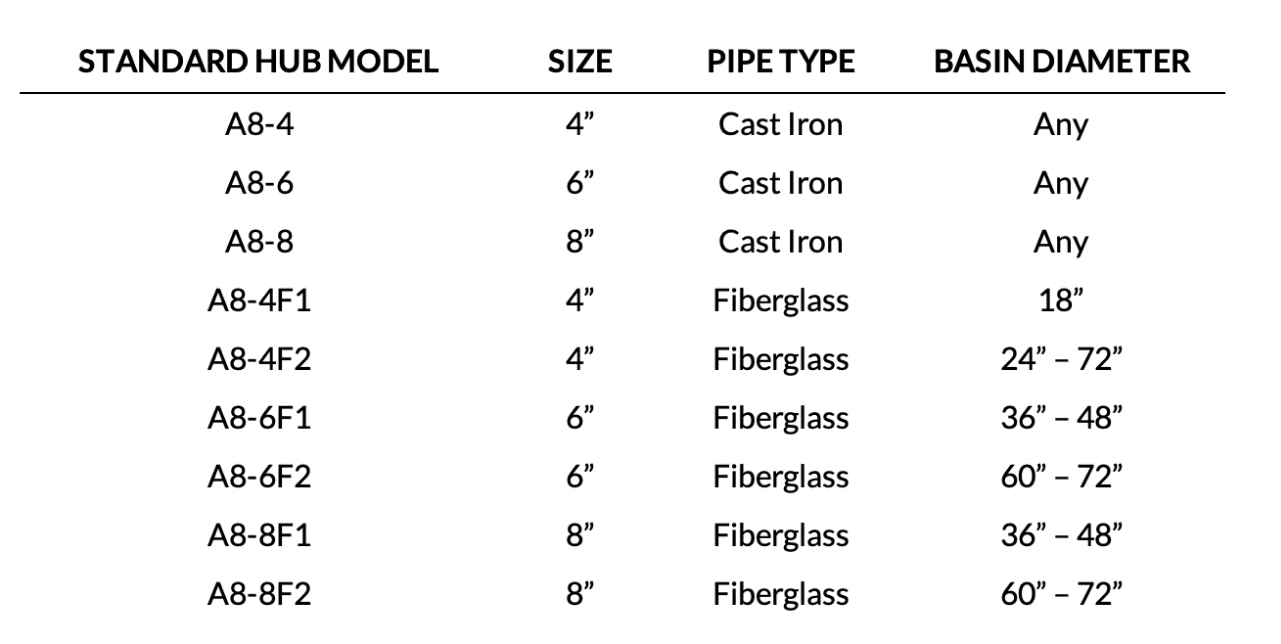
Required Inlet Connections:
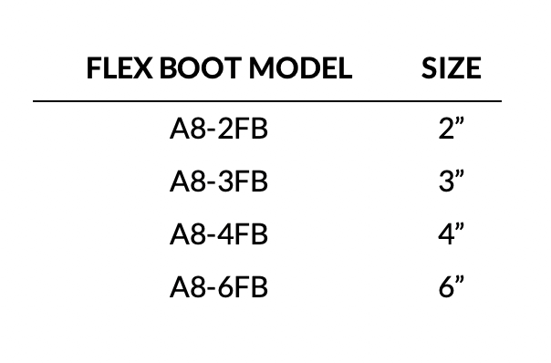
Fiberglass basins do not come with pre-installed inlets or outlets. These must be added and are shipped loose for installation in the field. The inlet hubs may be simple hubs or flex boot style.
Optional Discharge Hubs:
Discharge hubs are required If the discharge piping does not exit through the cover.
NOTES: 3” and 4” AAF OR CI inlets available. Cover ordered separately. B&G or AK brands available.
Flex Boot Style Inlet Hub
Sump and Basin Covers
The basin cover you select should match the diameter and material of construction required. The number of pumps and any base elbows supplied will also affect your selection.
Covers and Loading
Fiberglass covers are rated 120 lbs and will not support any the weight of a person walking on top of cover.
Steel covers are rated 300 lbs and can support the corresponding weight
There are also choices for traffic rated covers.
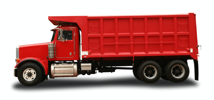
Traffic rated covers supplied by Bell & Gossett can be load rated covers if specified. The normal wheel rating of H-20 will provide a cover that will handle 16,000 lbs which is rated for “light duty” vehicles. Medium duty ratings of 16,000 to 40,000 lbs may be available. Please contact the R.L. Deppmann Company or your B&G representative.
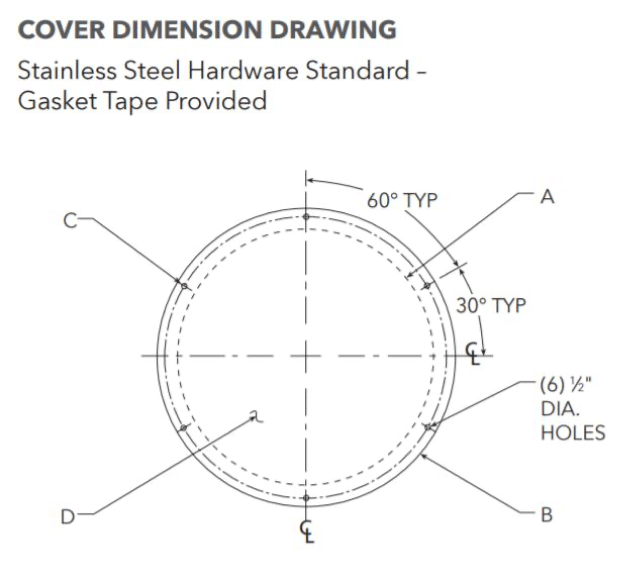
Round Sump Basin Covers
Most building trade applications will involve pumps 2” and greater with base elbows and guide rails. When the discharge piping and venting is through the cover, the single door hatch style solution is what you need.
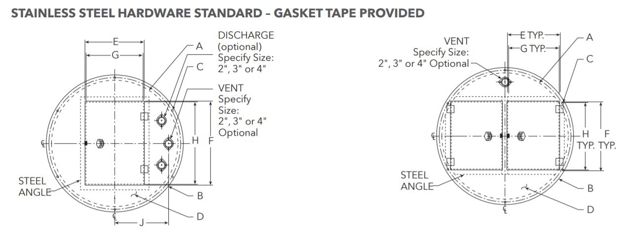
Please specify vent size and discharge sizes if required.
If all the piping and electrical is below grade, a solid cover may fit your needs. These are available in fiberglass or steel.
Rectangle Sump Cover with Doors
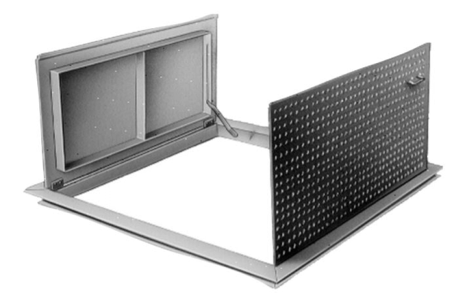
These may be single or double door. The standard construction is aluminum with stainless hardware. Stainless steel construction is available.
Other Basin Covers
There are several other cover choices if basins or sumps are shallow and no base elbows or guide rail systems are used. Please contact the R.L. Deppmann Company or your local B&G Representative for additional choices.
Trim Required For Basin Covers
Required Gas Tight:
In sewage applications, codes require the optional gas tight cover. Example: Michigan Plumbing Code (Section 712.3.2 Sump Pit) reads that the basin be “fitted with a gastight removeable cover”. In sump applications, we recommend gas tight if there could be odorous returns.
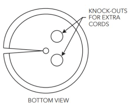
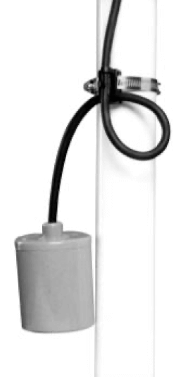
Required Cord Seal:
When the power wiring and float control wiring are through the basin cover, we suggest you purchase a model A8CS cord seal for each pump and one for the floats.
Required Correct Pipe Sizes:
It is important to provide the correct discharge and vent connection sizes when they are oriented through the cover. These are matched when the cover is being manufactured.
The pumps, basin, cover, base elbows, guide rails, floats, and connection sizes should all be ordered at the same time so the manufacturer can identify where the pipe connections will land as they exit through the cover.
Floats and Brackets
Pump Float Switches
Low horsepower pumps may use a pump float switch to directly start a pump or through a panel. The float switch is wide angle with a piggyback switch or bare wires.
Control Float Switches On Duplex Units
Control float switches must use a starter panel for the control of pumps. We recommend a duplex pumping system with each pump able to handle 100% of the load. We suggest three floats if you are not connecting alarms and pump run status to the building management system (BMS).
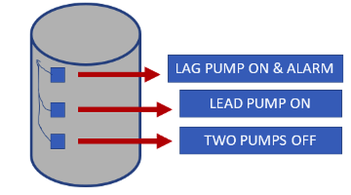
The lowest float turns all pumps off, the next float turns on the lead pump, which is alternated through the panel, the top float would turn on the lag or standby pump and should also turn on the alarm. If you use a fourth high level alarm it will be too late since the lead and lag pumps were not able to keep up with the load.
If the BMS will be used for pump run status, use a four-float system. The four-float system will have one float for the lag pump and one float for the alarm. Specify run status contacts and allow the BMS to indicate a possible lead pump failure if the lag pump operates.
Simplex units use three floats for pump off – pump on – alarm.
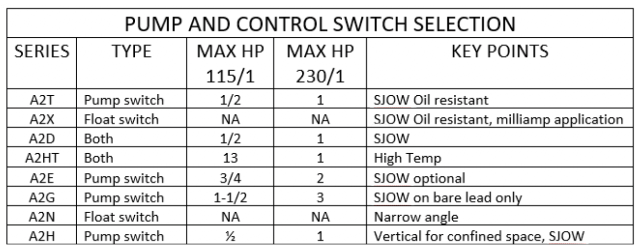
When there is a starter panel, we use the A2D33 model which is normally open with a 20-foot cord. If a weight is needed. The model becomes A2D33W.
Additional Information
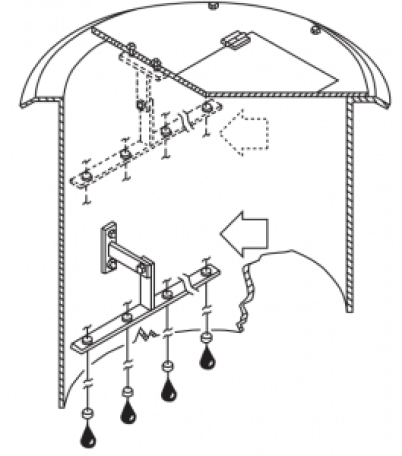
Control Float Brackets On Duplex Units
Float support may be accomplished in different ways. The floats should be located to avoid turbulence. Floats in MOST systems are normally attached to the discharge pipe. The pipe clamp is provided with the float switches.
If floats mounted to the discharge pipe will be too congested, a pump float bracket can be ordered. Model FSB3FB for 3 floats and FSB4FB for 4 floats. The bracket includes cord grips or snubbers.
You may need weights to avoid entanglement in tight basins. Add (1) A2WT SJ ELECTRO WEIGHT for each float when using a pump float bracket. Optionally you may order the floats with the weights provided.
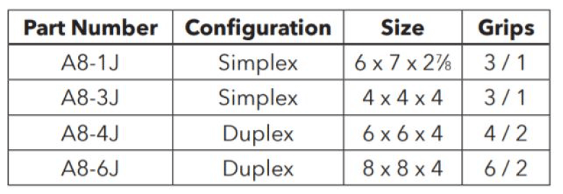
Junction Boxes
If panel is to be wall mounted or remote from the sump, a junction box is normally required. The B&G series A8 junction boxes are NEMA 4X construction and include cord grips.
Pump Float Bracket
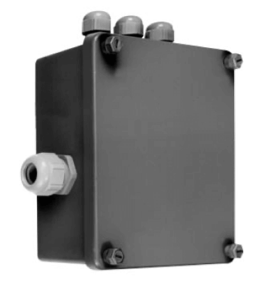
A8 Junction Box
Control Panels

Bell & Gossett Control panels are available for indoor or outdoor applications as well as explosion proof design.
What NEMA Design Do I Need?
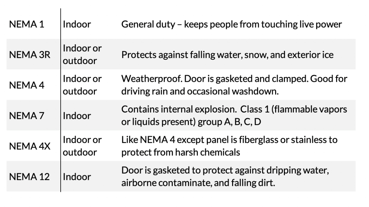
K series of single-phase panels – Indoor or outdoor
NEMA 4X, simplex or duplex, multiple voltage, includes 3 floats, very easy installation. Preconfigured.
Additional Information
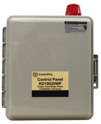
CSD AND CDD Series of Panels With Disconnect – Indoor or Outdoor
This is your go-to choice when a disconnect is needed.
Single main disconnect is pad-lockable in OFF position.
- Magnetic contacts
- Class 10 overloads
- Control transformer
- HOA
- Running lights
- Alternator
- Alarm horn
- Special seal fail
And many more options, including mini-CAS seal failure alarm system.
K series of single-phase panels – Indoor or outdoor
Additional Information
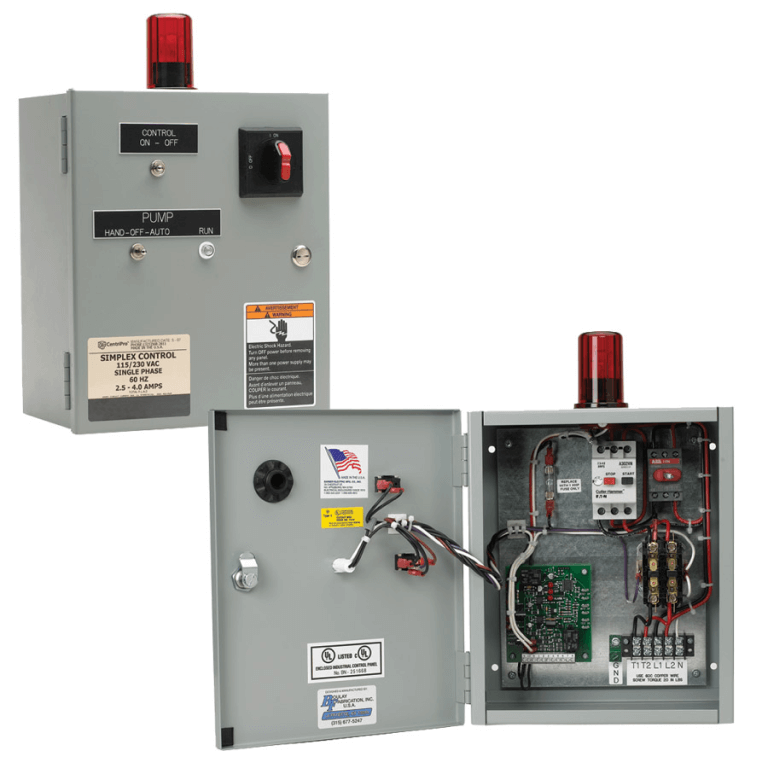
A3 Series of Panels – Indoor or Outdoor
Simplex, duplex, single or three phase. NEMA 1 (std), 3, 3R, 4, 4X, 12.
Options:
- Main Circuit Breakers
- High water alarm, with bell-horn-or light
- Guaranteed pump submergence
- Seal failure circuit
- Elapsed time meter
- Push to test
NOTE: Disconnect not included.
Additional Information
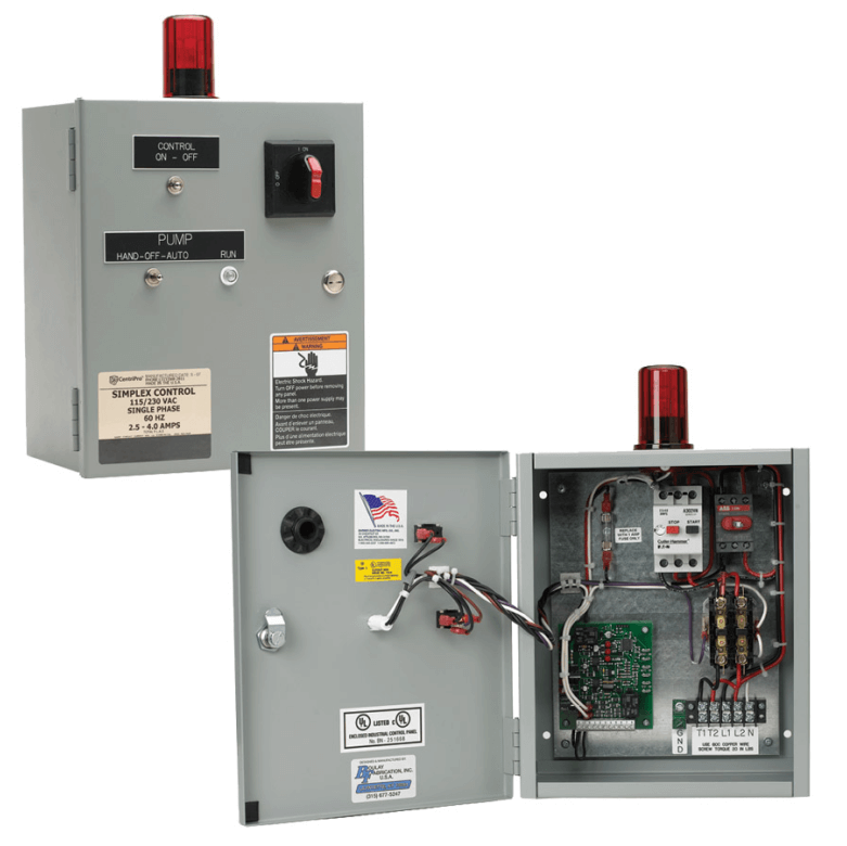
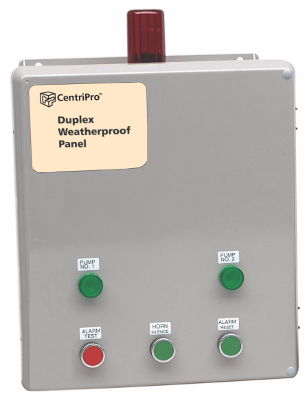
S100 & D100 Indoor Only Preconfigured
Simplex or Duplex: NEMA 1 with contactor, high level alarm light and horn with silencer switch, HOA.
See Bell & Gossett literature options for Simplex and Duplex Single Phase panels.
Additional Information
Need Assistance Selecting a Panel?
Call us at 800.589.6120 for help selecting the panel that works for you.
Design Assistance
This page containsuseful tools to assist the designer with calculations and selections:
Pump Head Calculations
Whether the fluid is water or sewage, the friction loss is normally calculated using the standard water tables or selection program. The exception to this is the discharge of grinder pumps. Grinders will discharge a water based slurry.
The following is applicable to sump, effluent, and sewage pump calculations.
Pump head in feet = friction loss in pipe and fittings + lift + pressure in the main + safety factor.
Friction Loss In Pipes and Fittings
Don’t forget the check and shutoff valves and fittings in the sump itself. Friction loss can be calculated using the B&G system syzer program.
Lift
Elevation to the main - Don’t forget the sump depth down to the pump. The depth can be approximated and corrected once the basin size is determined.
Pressure In The Main
Normally the pump is discharging into a gravity main. If pumping into a pressurized main, you will need to add the appropriate head to overcome this pressure.
Pump Flow Rate Safety or Surge Factors
The safety factors or surge allowance you use will affect both the size of the pump and the diameter of the basin. The normal safety or surge factors are 1.5, 2, and even 3 times the in flow. Your choice is dependent on the quality of the calculations and unexpected surges. All said, we normally recommend using a factor of 2X for the flow rate.
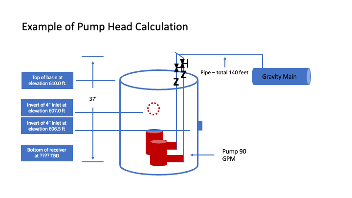
Example of Pump Head Calculation
Additional Information
Example of Friction Loss
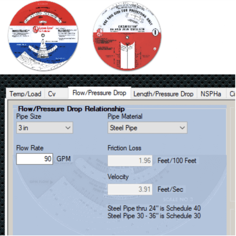
Step 1: Check pipe sizing chart below. Select a pipe size and insert into the B&G system syzer program. The flow rate with safety is 90 GPM.
Step 2: Add fittings and valves.
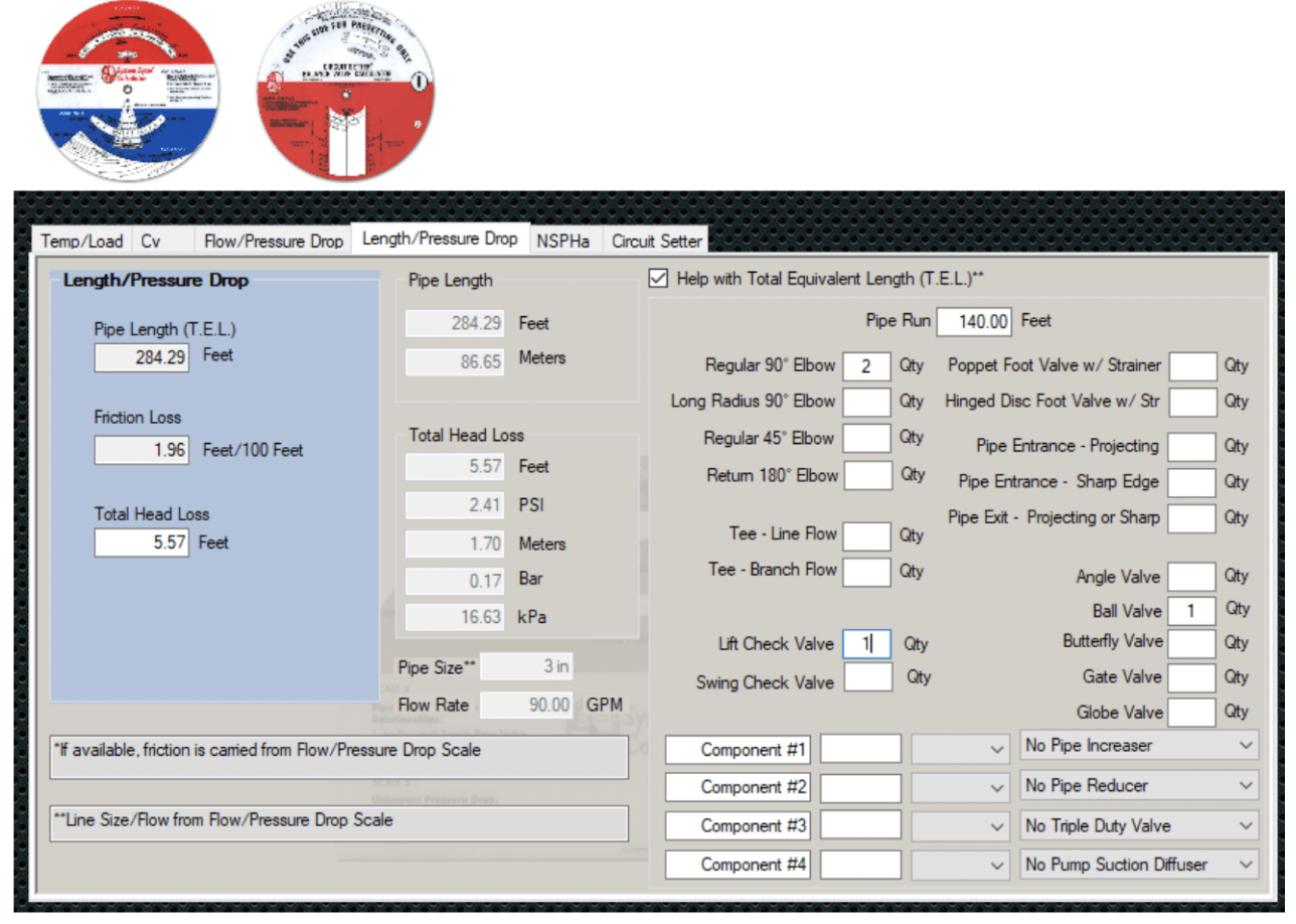
Step 3: Add the lift (5.6 from above plus 37 feet lift = 42.6’)
Step 4: Add pressure in the main (42.6 plus 0 = 42.6’)
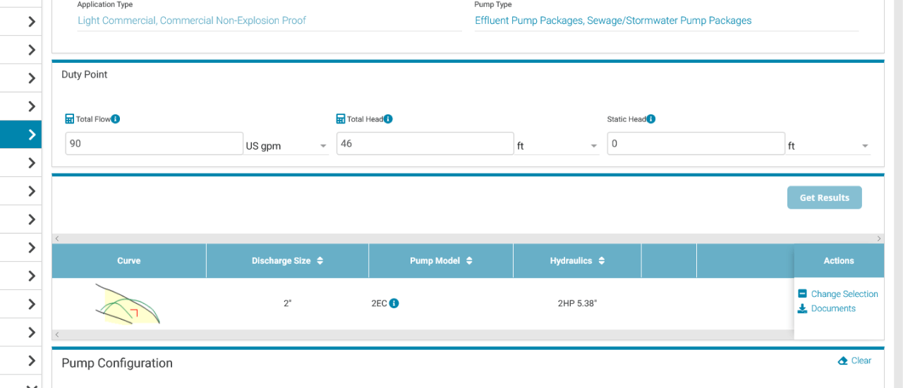
Step 5: Add safety factor. The lift is fixed so let’s use 1.5 on the friction (5.6 X 1.5 = 8.4 + 37 feet lift ≈ 46 feet. Select pump for 90 GPM at 46 feet.
Pump Selection:
Sump, effluent, and sewage pumps may be selected using the Bell & Gossett esp-Systemwize program.
Our selection program will provide the user with many pump choices to meet a given capacity. Choice of pump style and trim will affect the first cost and expected life of the pump. Depending on the needs of your client and the application, you may want a less expensive or more expensive choice.
Pump Choice:
Check our webpage Sump & Effluent or Sewage and Vortex to determine the good, better, or best pump style choice fits the project.
Program Tips:
- Register and create a password to download the submittal data once a pump is selected.
- Under pump type select all but elevator and grinder unless those fit you needs. Under application type select light commercial under you need explosion proof.
Additional Information
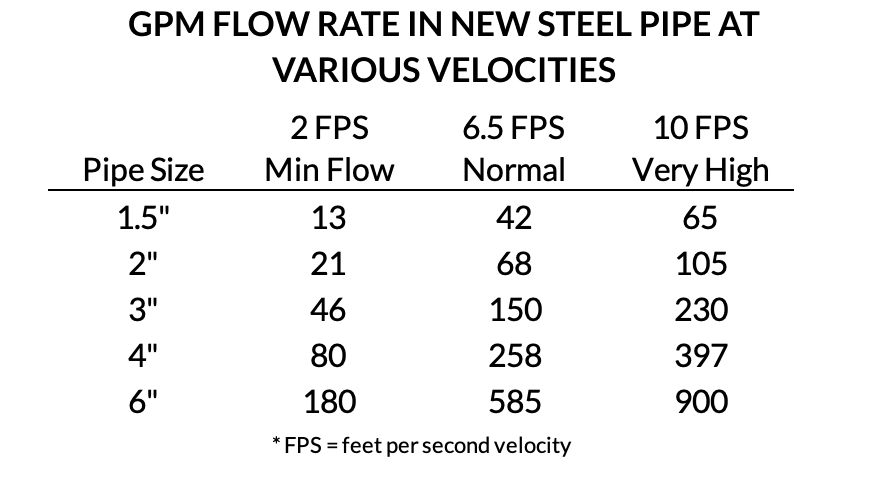
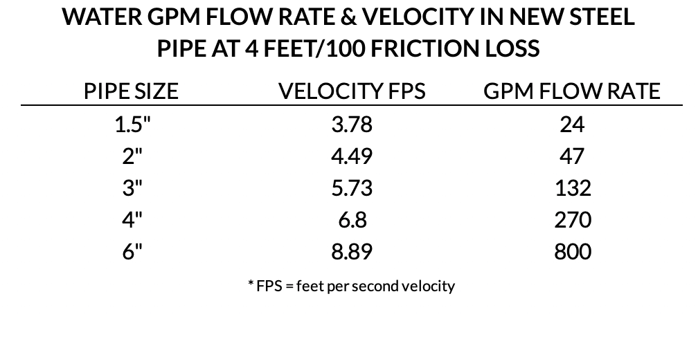
Pipe Sizing
The size of the pump and pipe will be a factor in determining the basin diameter. Often the “rule of thumb” is a pipe size that results in 4.0 feet/100 friction loss. This comes from the hydronic design world. This choice provides lower pump head and horsepower but larger basins or sumps. There is no reasonable published limit to the velocity in steel or PVC pipe. Here is a handy table.
Basin Sizing
The following tips are offered for fiberglass below grade basins installed inside the building with the pipe exiting through the cover. The first purpose of the basin volume is to hold the surge of fluid from the drains and allow enough storage to meet a minimum run time. The second purpose is to flush the discharge pipe completely during each cycle.
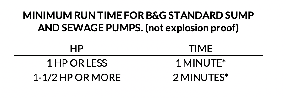
The volume of storage should provide a minimum run time at the rated flow rate per the table above.
The volume of fluid in the discharge pipe should be completely changed during every pump cycle. This may require a longer cycle time in systems with longer pipe lengths and/or larger pipe lengths.
Minimum Diameter:
The basin must fit the pumps with the base elbow and space the pipe properly to match the elbow and tee dimensions when piped outside the basin. There must also be room for the floats without having them in the direct flow of the incoming fluids.
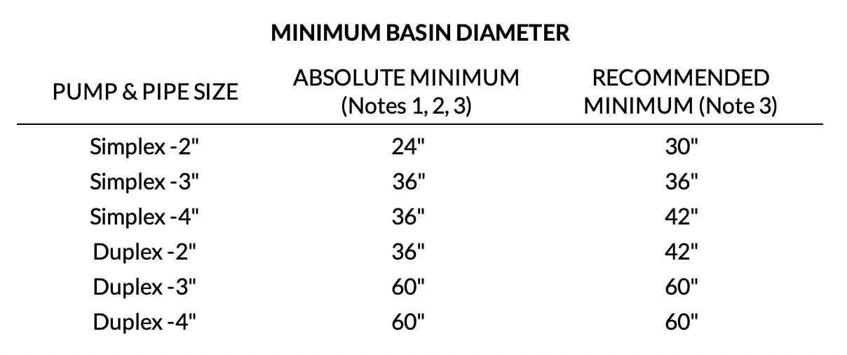
Note 1: The absolute minimum assumes the check and shutoff valves are located outside of the basin.
Note 2: If the basin is selected at the absolute minimum and will be field assembled, we recommend a false bottom be specified.
Note 3: if the basin is over 6 feet deep, we recommend a factory installed system or a basin specified with a false bottom.
Basin Volume – The Steps For Sizing
Step 1:
Determine the minimum usable volume needed (REQUIRED VOLUME). Check the time in the minimum run table above. Determine total volume of discharge piping and determine if the pipe will completely flush in a cycle time from the table. If not, increase the usable volume so the pump runs longer.
Step 2:
Determine pump off level (PUMP OFF LEVEL). B&G pumps can run continuously if the motor is completely submerged. See submergence table for the minimum level for the pump selected.
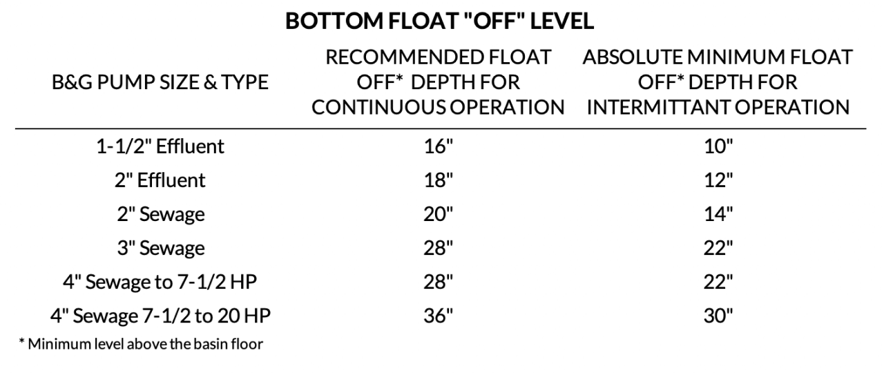
Note: Consult the manufacturer's literature for explosion proof motor requirements
Step 3:
Select the RECOMMENDED basin diameter from chart above.
Step 4:
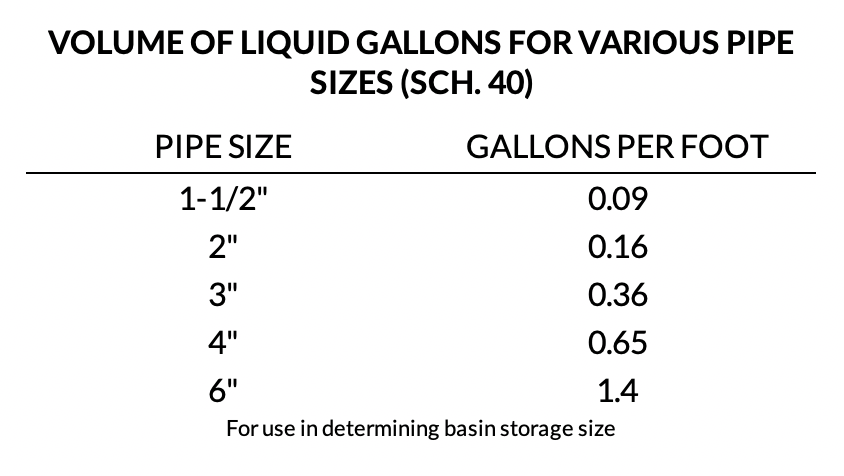
Determine height of usable storage in inches. Find the gallons per inch from the Basin & Trim page. REQUIRED VOLUME/ (gallons per inch)
Step 5:
Determine the basin height to the LEAD PUMP ON LEVEL. This is the results from item 4 above plus the PUMP OFF LEVEL, item 2.
Step 6: Three float system
Determine total height: LEAD PUMP ON LEVEL +6” to (ALARM/LAG ON LEVEL) + 6” to invert (bottom) of the LOWEST INLET + HEIGHT TO THE FLOOR. Round this number to the next number divisible by 6.
Step 6: Four float system
Determine total height: LEAD PUMP ON LEVEL +6” to LAG ON LEVEL +6” to alarm on level + 6” to invert (bottom) of the LOWEST INLET + HEIGHT TO THE FLOOR. Round this number to the next number divisible by 6.
Step 7:
If the depth required is too deep for the water table or too high compared to the ceiling in the room it will be installed, move to a wider basin.
Example of Basin Sizing
Using the same example shown above:
1. REQUIRED VOLUME: Pump is 2 HP so 90 GPM X 2 minutes = 180 gallons
2. PUMP OFF LEVEL = 18” for 2” effluent duplex pumps
3. SELECT BASIN DIAMETER = 48” from table above.
4. REQUIRED VOLUME: 180/7.50 gallons per inch = 24"
5. BASIN HEIGHT to LEAD PUMP ON LEVEL = 24" + 18" = 42"
6. TOTAL HEIGHT: 42" + 6" + 6" +42" = 96"
7. VERIFY DEPTH IS ACCEPTABLE FOR WATER TABLE AND IS NOT TOO HIGH FOR THE CEILING: OK
8. BASIN IS 48" x 96"
Control Panels
FLOAT CONTROL FOR LARGER SYSTEMS
A 3-float system (Pumps off- lead pump on- lag pump on and alarm on) is suggested for duplex pumping when no building management system (BMS) interface is available. If the BMS interface is available, use a 4-float system (Pumps off – lead pump on – lag pump on – alarm on).
Specification for float control:
“When the control diagrams indicate alarm contact closure and pump run status closure interface with the building management system (BMS), use a four-float control system for pump operation. Lowest level float will turn the pumps off. Next float up will operate the lead pump and close a set of BMS run status dry contacts. The next level float will operate the lag pump and close a set of run status contacts. The highest-level float will operate the audio and visual alarm in the control panel as well as a contact closure interface with the BMS system.
If no BMS control interface detail is indicated in the plans, provide a three-float control system for pump operation. Lowest level float will turn the pumps off. Next float up will operate the lead pump. The highest-level float will operate the lag pump and operate the audio and visual alarm in the control panel”
CONTROL PANELS
The control or starter panel may be shown in the ESP-Systemwize program from Bell & Gossett. Here is a quick summary of suggested options with their models.
Elevator Sump Pumps:
Special panel as outlined in that webpage
Grinder Sewage Pumps:
Special panel as outlined in that webpage
Effluent and Sewage Pumps:
CSD (SIMPLEX) and CDD (Duplex) - NEMA 4X or NEMA 1 with main lockable disconnect and many options.
Series D (Duplex) - Control panel with NO disconnect
Interested in a budget price for a factory assembled system?
Call the R.L. Deppmann Company or your Bell & Gossett representative.