Printer Friendly (PDF)
 Today, the R. L. Deppmann Company Monday Morning Minutes starts a series of articles on sump and sewage system sizing tips. The pump head calculations for sump and sewage applications are not very complex. There will be a large difference in the friction losses depending on whether you design for a new pipe or old pipe.
Pipe Friction Loss Charts and the “C” Value
Many of the pipe friction loss charts and calculators in hydronic and plumbing systems are derived from the Hazen-Williams formula. Where does this formula come from? Many of you know I am interested in genealogy so humor me for a paragraph.
Allen Hazen was an engineer born in 1869 near Norwich, Vermont and graduated from the New Hampshire College of Agriculture and Mechanical Arts. Gardner Stewart Williams was born in 1866 in Saginaw, Michigan and graduated from the University of Michigan. In the early 1900s, these two civil engineers created the Hazen-Williams formula and developed a series of “C” factors, used to this day, to describe the roughness of pipe in fluid dynamics.
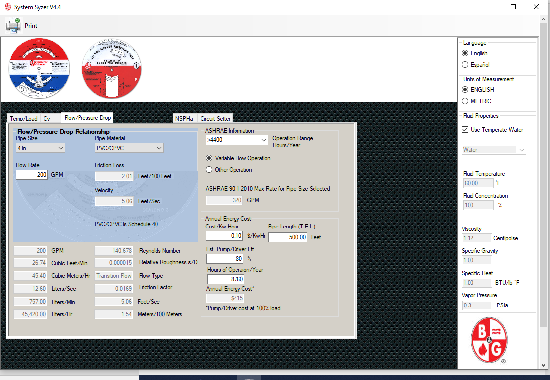
The “C” value has a large effect on the friction head in pump calculations. Let’s look at an example. Assume you determined the flow rate of the sewage lift pump to be 200 GPM. The Submersible Sewage Pumping Systems (SWPA) handbook has a table 3-21 for new plastic pipe based on C-150 and a table 3-28 based on 15-year-old cast iron pipe with C=100. For 4” pipe at 200 GPM, the clean pipe in table 3-21 has a loss of 2.06 feet per 100 feet. The old cast iron pipe shows a friction loss of 4.40 feet per 100 feet. This is over 100% difference between the two numbers!
What Difference Does It Really Make?
A reasonable engineer may challenge, what difference does it make whether we use C=100 or C=150 in sump and sewage piping systems? In building service sump, effluent, and sewage pump selection the length of pipe is normally very short. The movement on the pump curve may be very slight. The pipe is new to begin with and old later. When does it make a difference? It makes a difference when something is not working right. Let me voice my opinion.
Minimum and Maximum Velocities in Pumped Sump and Sewage Systems
Let’s start with three basic rules.
Rule 1: The minimum velocity in a pipe for pumped sump and sewage applications is 2.0 feet per second (FPS). This is called the scouring velocity. Unlike the gravity flow mains, this application has a pipe filled with water and it is under pressure. The scouring velocity is named because that it what it does. The fluid is moving fast enough to keep the pipe reasonably clean of buildup.
Rule 2: The maximum velocity is 10 FPS. Steel, galvanized, and a plastic pipe has no published maximum velocity that I have found. What I do know is that manufacturers of check valves normally want the velocity limited to 10 FPS to avoid chatter and wear. Since these systems have a check valve, the maximum is 10 FPS.
Rule 3: The pump should run long enough to completely change the fluid in the discharge pipe every cycle. This rule keeps the fluid and its contents from sitting in the pipe too long. If I am flowing 50 GPM and the total volume of the discharge pipe to the main is 50 gallons, the pump should run at least 1 minute so all the water is changed. There are other rules for the minimum run time. Visit our Sump and Sewage pages on the R. l. Deppmann Plumbing Design website.
Norm’s Suggestion for Building Sump and Sewage Pump Friction Loss
I suggest we use the C=150 charts and add a safety factor to them. In this case, the safety factor will be used to accommodate any slight buildup in the piping system over time. By sizing in this way, the pump operation point is known when the pump is commissioned. We know the horsepower and location on the curve. We can use system curves to identify where we are operating with and without the safety factor.
The C=150 plus a safety factor is a hybrid of the new and old pipe friction losses. The real advantage is a clear understanding of the maximum horsepower needed today. Although it is doubtful, if the pipe corrodes over time, the horsepower will drop. The combination of safety factors in the friction loss and the safety factors in the flow rate will cover future conditions.
Bell & Gossett and Gould also recommends the C-150 charts in the Wastewater Technical Manual. This is also the friction loss used in the B&G system syzer. Whether you agree with my suggestion or not, you can use the B&G electronic System Syzer and speed up the pump head calculations and documentation. I will provide the correction factors to the system syzer for other “C” values in the next R. L. Deppmann Monday Morning Minutes.