Printer Friendly (PDF)
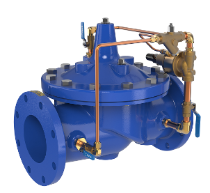
Photo Credit: Cla-Val
Minimum pump flow rate is critical to the trouble-free operation and longevity of the centrifugal pump. The pressure sustaining valve or back pressure valve is one method used for decades to protect the pump. This method has its place in the world of pumping but can be, and often is, misapplied.
Self-Contained Pilot Operated Pressure Reducing Valve
A back pressure relief valve or pressure sustaining valve is simply a self-contained pressure regulating valve. The Cla-Val 50-01 starts with the same Hytrol main valve as the 90-01 pressure-reducing valves we used on the Bell & Gossett constant speed pressure booster systems for over 60 years. The pressure-reducing valve senses the outlet pressure and regulated the orifice area of the main valve to maintain a constant outlet pressure.
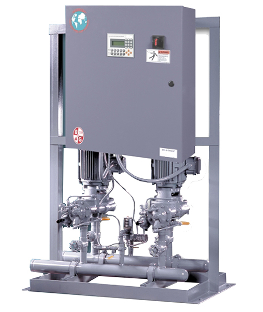
The pilot helps fine-tune the pressure changes and helps when there are low flow rates. We all know that pressure booster systems spend a lot of time at low flow rates. The old B&G 70M pressure booster shown above has angle pattern pressure-reducing valves on the outlet of the pumps.
This same valve is used for a pressure-sustaining use.
Cla-Val Model 50-01 Pressure Sustaining Valve
The pressure-sustaining valve is also known as a back pressure control valve. Here the manufacturer uses the same valve but in a reverse-acting mode. In addition, the sensor location is changed to the inlet of the valve.
The valve is field set during commissioning to a given pressure. That is the maximum pressure you want to see at the inlet of the valve. If the pressure increases, the valve opens to flow water through the valve to a lower-pressure system. This valve was used extensively in water works systems where the distribution or booster pumps were constant speed with a widely varying flow rate.
The Constant Speed Water Works Pump and the 50-01 Valve
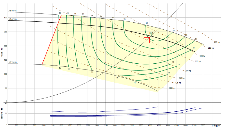
The curve, from esp-systemwize, shown above is a constant speed Bell & Gossett horizontal split case 8” by 10” pump with a capacity of 4000 GPM at 231 feet or 100 PSIG. This could very well be a typical pump at the water works pumping station.
We know in the middle of the night that the flow rate will not be at the design of 4000 GPM. In fact, knowing how much safety factor is required to anticipate the unknown, the flow rate of this pump may never be above half of the design flow rate. Look at the curve and the red line towards the left shutoff. That is the minimum flow rate required of this pump. The minimum flow rate of this constant speed pump is 1414 GPM. At that point, the pressure would be about 280 feet or about 121 PSIG. Both the minimum flow rate and the pressure at that point may be issues for the system. Enter the need for a back pressure relief valve.
Operation of the Back Pressure Relief or Pressure Sustaining Valve in a Constant Speed Pump
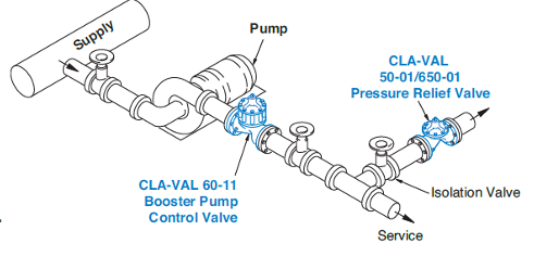
Photo Credit: Cla-Val
The example shown above may be typical. In a water works pumping station the suction pressure is constant from a tank. If we assume the suction pressure is 10 PSIG, the example pump shown above would produce 110 PSIG at the discharge when delivering 4000 GPM. The Cla-Val 50-01 pressure sustain valve would be located at the discharge of the pump and would bypass flow rate back to the tank to maintain the pressure and flow rate.
Assume the required flow of the municipality was 1000 GPM. At that flow rate the outlet pressure would be the 285 feet of the pump plus the 10 PSIG inlet pressure or 145 PSIG. With a pressure-sustaining valve we would never get to that point. The valve would be open and bypassing the (4000 – 1000 =) 3000 GPM back to the tank. This would keep the pump at 4000 GPM and the pressure at 110 PSIG. It satisfies the system need of 110 PSIG and the pump need to maintain a flow above 1414 GPM.
Be Careful! It Will Not Work in Closed Hydronic Systems
Today’s pumps normally have variable speed drives and controls. This single set point valve may not work in those systems. Remember, the valve is set at one pressure and will open or close based on that pressure. In addition, the temperature will change in a closed system and the pressure will follow that temperature change. More about this in the next R. L. Deppmann Monday Morning Minutes.