 Previously, the R. L. Deppmann Monday Morning Minutes looked at pump location in a primary-variable boiler heating system. We made a very definitive statement about the pump location. Today we look at primary-secondary systems. Whether the system is variable primary-variable secondary or constant primary-variable secondary, the question we’ll answer is where should the primary pump be located?
Does the pump care where it is at in a closed hydronic system?
We started with this question last week and made two statements regarding pump locations.
Statement 1: The pump does not really care where it is at in a low-pressure closed hydronic system. In that blog, we also identified a big concern about the pump location in relation to the expansion tank.
Statement 2: The pump is concerned about where it is in relation to the expansion tank and wants to pump away from the tank.
Primary Secondary Basic Concepts
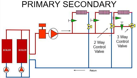
It would be helpful to understand a couple of basic concepts of primary secondary (P-S) hydronic heating systems while reading this blog. The key to P-S design is the green-colored pipe in the diagram above. This is called the common pipe and is a short 12” long piece of pipe with low velocity. The idea is to make the pressure drop in the common pipe so low that it has no effect on the operational flow rate of any of the pumps.
As the flow rate changes in the secondary system, it has no effect on the flow rate through the boilers in the primary system.
If you want more information on primary-secondary terms and rules, visit many of the previous blogs.
Hydronic Primary-Secondary Piping – How Important are the Two Close Tees?
Hydronic System Primary-Secondary Rules-Decoupling Systems
Primary Secondary Piping and Water Tube Boiler Cycling
Hydronic Condensing Boiler Heating Buffer Tanks – Part 1 of 3 – Location
Locating the Primary Pump on the Inlet of the Boiler 
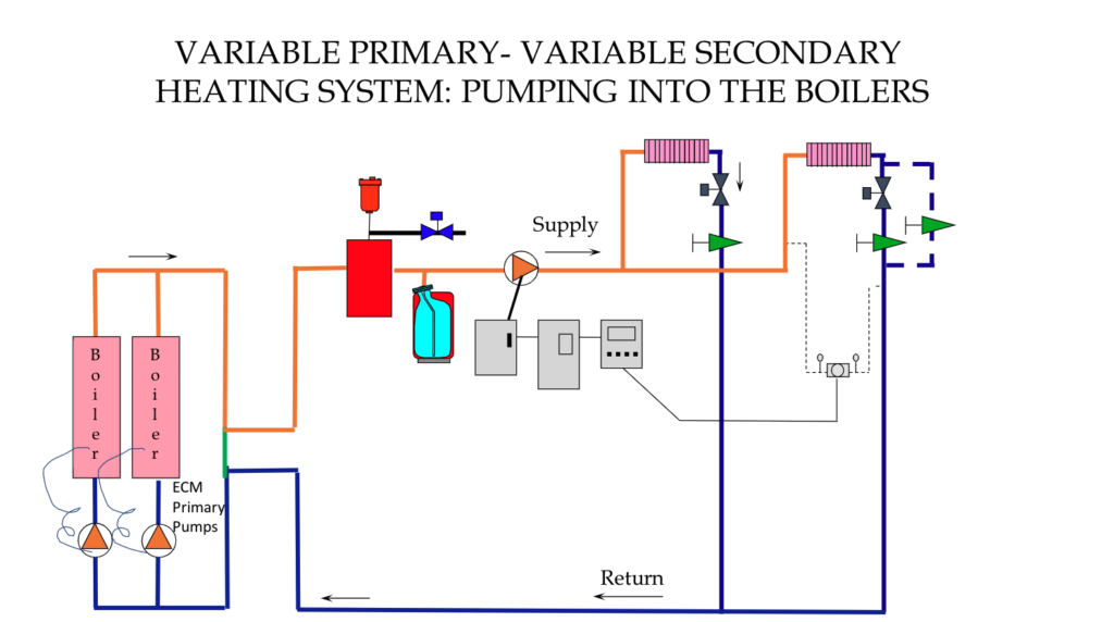
The image above shows a variable-primary-variable-secondary heating system with the primary pumps pumping into the boilers. The substantial difference between this and the primary variable system is the addition of the lower head boiler pumps and the low pressure drop common pipe.
The advantages: location of the expansion tank and boiler pressure. The expansion tank is located at the inlet of the higher head pressure secondary pumps. This is good since we are pumping away from the point of no pressure change. The tank and air separator are at the lowest pressure and highest temperature point which is great for air separation.
The primary pump may look as if it is pumping into the tank. If you look closely, the common pipe has no pressure drop and there are only a few feet of pipe from the common pipe to the tank. The expansion tank pressure is close to the pressure in the common pipe, so we are pumping the primary pumps away from the point of no pressure change. This also makes sense because most of the pressure drop in the primary loop is the boiler.
The pump pressure is increasing the pressure in the boiler. A fact that many boiler manufacturers like.
Is the Pressure Relief Valve Operating with This Pump Location?
I made a statement about the relationship between the relief valve, the tank, and the pump location in the primary variable blog. How will the boiler pressure follow temperature in this primary-secondary system? Start with the same original design criteria for the expansion tank from the last blog.
Use an example of a system with 2000 gallons of water with a design of 180⁰F to 140⁰F. We will assume a fill pressure of 20 PSIG. Assume the boilers we use will have 100 PSIG relief valve set pressures. The primary pump head is 25 feet at design. We will use the esp-Systemwize program from B&G to size the tanks.
Just as in the primary variable system, the expansion tank remains a B&G B400 which is 30” x 50” high.
When the primary pump is pumping into the boiler, what happens if the system is in a run-away condition, but the pump is at minimum speed at only 2 PSIG? The primary pump inlet would require 88 PSIG for the pressure relief valve to start to weep. (100 PSIG relief less 10% is 90 PSIG. 90 PSIG minus the pumps 2 PSIG is 88 PSIG.) The B400 tank will now allow the pressure in the tank to rise to 88 PSIG if the temperature jumps to 195⁰F. The pressure relief valve is active, and the run-away temperature will not steam.
The ASME pressure relief valve will open if the temperature controls on the boiler fail.
Don’t Locate the Primary Pump on the Outlet of the Boiler
Locating the primary pump on the outlet of the boiler in a primary-secondary application is not recommended. Now the primary pump is pumping into the point of no pressure change. In our example, the fill pressure is 20 PSIG, and the pump pressure is 11 PSIG (25 feet). The boiler at the pump suction would be at 9 PSIG. If the fill pressure was lower at 12 PSIG, that boiler pressure would be 3 PSIG and the boiler manufacturer would not like it.
Conclusions About Pump Locations with Boilers
The conclusion from this article and the previous blog is simple. Pump locations are subject to the type of system you are designing.
Primary Variable Pumping: In a primary variable system, there is no dedicated boiler circulating pump. The system pump also pumps the boiler.
Statement: The preferred location of the pump in a primary variable heating system is on the outlet of the boilers.
Primary-Secondary Pumping: In a primary-secondary system, there is a dedicated boiler circulating the primary pump as well as a separate system secondary pump. There is a common pipe designed for less than 1 foot of pressure drop which separates the two pumping systems.
Statement: The preferred location of the secondary pump in a primary-secondary heating system is on the outlet of the boilers. The preferred location of the primary pump in a primary-secondary heating system is on the inlet to the boilers.
The question we are often asked is which system is better, primary variable or primary secondary? The answer is “it depends.” That will be the subject of the next R. L. Deppmann Monday Morning Minutes.


