Printer Friendly (PDF)
In part 1 of this series we offered an example condenser water pumping system. The design of this example is 800 GPM per condenser for a total of 1600 GPM with the third condenser as a standby. The tower elevation—or lift—is 10 feet, the condenser with the two-way valve and balance valve has 20 feet of pressure drop, and the common piping with any safety factor has 20 feet of pressure drop
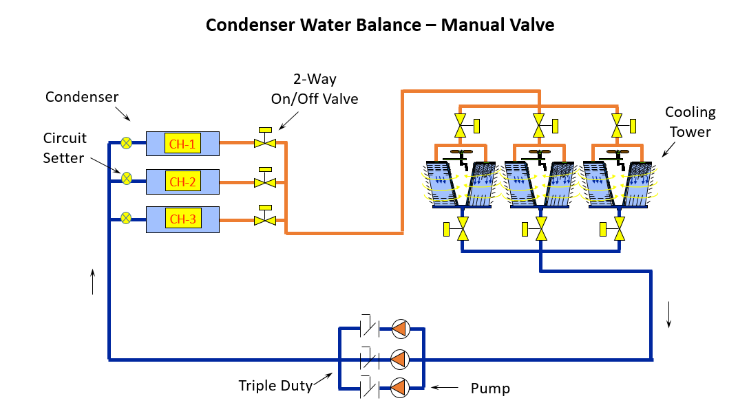
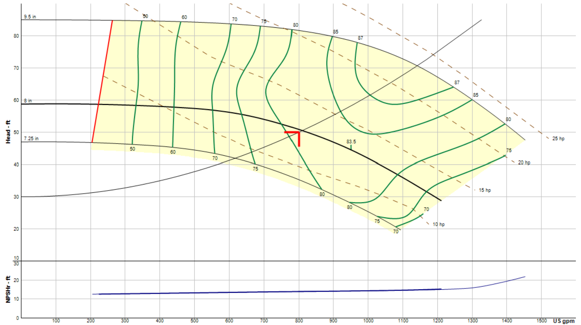
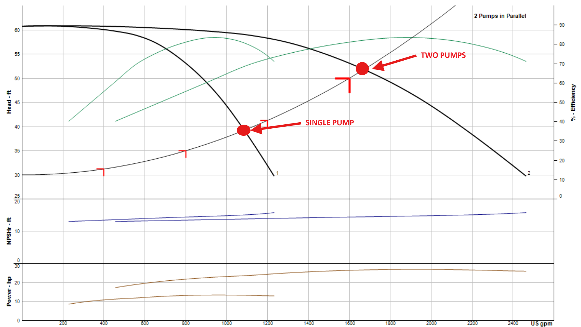
In parallel pumping, the single pump operation is at the intersection of the single pump curve and the system curve. In this example, we want the operation to be 800 GPM at 37.5 ft, but there is a problem. The intersection of the two curves is not at 800 GPM at 37.5 ft—it’s at about 1100 GPM at 39 ft. When one pump shuts down and the two-way valve closes, the flow rate will be 37% above the design flow rate of the condenser. If this exceeds the condenser maximum flow rate, the manufacturer may void the warranty on a very expensive piece of equipment. What can we do about this?
There are two solutions that we can use, and each one has its advantages.
Use Flow-Limiting Balance Valves Instead of Manual Balance Valves
The first possibility is to physically stop the flow rate at any condenser from exceeding the design flow rate by using a flow-limiting balance valve. Two examples of these valves are the Bell and Gossett Circuit Sentry and the Griswold 150 Wafer automatic FCV.
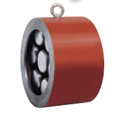
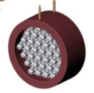
Left: Bell & Gossett Circuit Sentry. Right: Griswold wafer
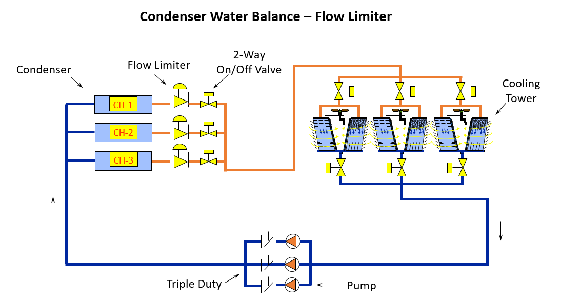
There are two main advantages of these products in this application. Since the valves replace the manual balance valves and do not need any electrical or controls, the first cost is attractive. They are factory set for a given flow rate—and when the system pump attempts to increase the flow rate, the valve throttles to maintain the flow.
There are three main disadvantages:
- The valves normally have a larger minimum pressure drop of 2 to 5 PSIG at design flow rate.
- The valve selection tends to be larger than the pipe size. In order to keep the pressure drop lower, we normally select a larger valve. Since there are no pipe diameters required for accuracy, reducing flanges might be used.
- The valves have fine openings and consideration should be given to dirt control in the open tower system.
Use a Danfoss Variable-Speed Drive for the Pumps with Simple Contact Closure Control
Another solution involves the use of variable-speed drives, in which the starter is replaced with a drive. Danfoss offers an opportunity to have a contact closure within the drive, which sets the drive at a given speed. When operating with two pumps, the controls close a set of contacts for full-speed, less safety factors. When operating with one pump, the controls close a second set of contacts to operate at the lower speed needed for single pump operation.
I recommend the same set of drive contacts be closed at each pump, based on whether one or two chillers are on. The enable contacts in the drive determine if the pump should operate. By having the same contacts closed in all the drives, you avoid the possibility of operating two pumps in parallel with different speeds, which could deadhead a pump and cause damage.
The advantages of this control vs. the automatic flow limiter valve are reduced pressure drop and energy savings. The disadvantages are the cost of control contact closure and the possibility of added motor protection due to the use of drives.
Next week the R L Deppmann Monday Morning Minutes will look at the advantages of adding a differential pressure switch to this application.