Printer Friendly (PDF)
Applying a single constant-speed pump for each condenser in a chilled water application is a normal design for the HVAC engineer. The chiller manufacturers suggest piping the pumps with a common header and activating each pump as the condensers are staged on. There’s a hidden problem which, if not addressed, may cause major problems. Today’s Monday Morning Minutes post begins a three-part series on the problems and the solutions.
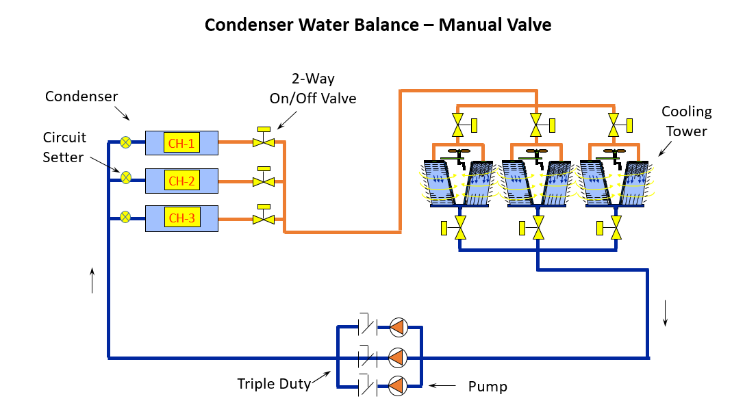
Parallel Pumping in a Typical Cooling Tower System
Below is a typical cooling tower system sketch. As each chiller is enabled, the tower pump is started and, once flow is proven across the condenser, the chiller is started. When CH-1 is enabled, pump P-1 is started. When chiller CH-2 is enabled, pump P-2 is started. The flow rate of each pump is matched to the condenser flow rate. ASHRAE 90.1-2013 energy standards advocate stopping flow in any heat transfer source that is not active, so the sketch has two-way valves at each condenser and tower. The two-way valves leaving the tower may or may not be used, depending on the brand and whether a properly sized equalizing line exists.
Parallel Pumping Example
Let’s look at an example and see how the pump operates as pumps are staged on. For simplicity, the example will assume one chiller and pump are standby and only two are operating at design. Assume 800 GPM per condenser for a total of 1600 GPM. Assume the tower elevation or lift is 10 feet, the condenser (including the two-way valve and balance valve) has 20 feet of pressure drop, and the common piping with any safety factor has 20 feet of pressure drop.
10’ + 20’ + 20’ = 50’ at 800 GPM for each pump
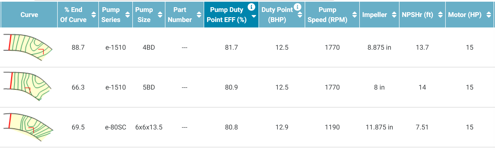
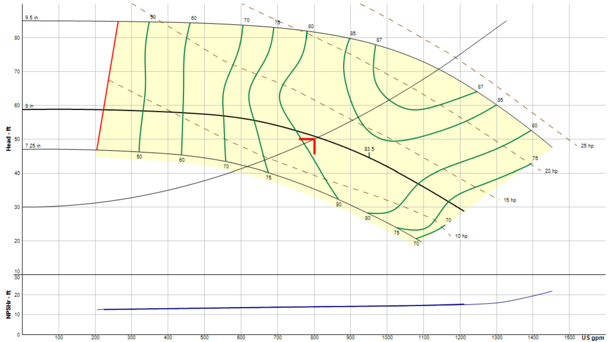
I used the Bell and Gossett ESP SystemWize selection program and looked at both e1510 base-mounted end suction and e80SC vertical inline pump selections. Clearly, the e1510-5BD has a better efficiency and the NPSH met my needs, so I chose that model.
The pumps are piped in parallel, but the operation required is at either 800 GPM or 1600 GPM, depending on the number of chillers needed. Whether one pump or two pumps are operating, the tower lift remains at 10 feet so that is a fixed head. Since the system requires a constant flow of 800 GPM at each condenser, the pressure drop across the condenser should also be fixed at 20 feet. The variable head in the system is 20 feet in the common piping.
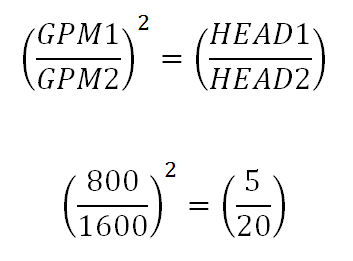
The second affinity law states that the head varies as the square of the flow rate, so if my variable head is 20 feet at 1600 GPM, the common head required at 800 GPM is 5 feet.
Therefore, in this example, at 800 GPM the head should be 10’ + 20’ + 5’ = 35’. Let’s look at the parallel pump curve. If there were no two-way valves on the condenser, the control head in an open system would simply be the lift, or 10 feet. Since the two-way valve will be closed on one condenser, we could represent the control head as 10’ plus the 20’ across the condenser for a total of 30’.
The Hidden Problem
In parallel pumping, the single pump operation is at the intersection of the single pump curve and the system curve. In this example, we want the operation to be 800 GPM at 35’. This is where the hidden problem appears. The intersection of the two curves is not at 800 GPM at 35’, it is at about 1100 GPM at 39’. When one pump shuts down and the two-way valve closes, the flow rate will be 37% above the design of the condenser. If this exceeds the condenser maximum flow rate, the manufacturer may void the warranty on a very expensive piece of equipment.
What can we do about this? You guessed it. Come back next week for part 2.