Printer Friendly (PDF)
 Happy New Year 2021! I pray that we all have a healthy year and see the return of normal lifestyles. This final blog in this series will recap some of the best piping practices suggested by the Hydraulic Institute and Xylem Bell & Gossett.
Over the last several weeks we discussed the feared NPSH and showed it is rarely an issue at design conditions. Often, noise and pressure problems are caused by air in the suction piping system. The suction pipe, in many cooling pumping systems, is under very little pressure. In fact, the suction of the pump could be under a vacuum.
AIR WILL NOT VENT FROM A VACUUM TO ATMOSPHERE!
Bell & Gossett (B&G) has several piping rule suggestions for cooling tower pump suctions.
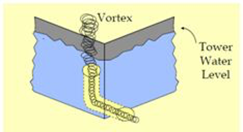
RECOMMENDATION #1: Always specify an anti-vortex baffle, sometimes called a doghouse, in the tower outlets.
Towers normally have very low storage heights of water in the basin. Any vortex that starts will reduce the flow rate and pull air into the piping system.
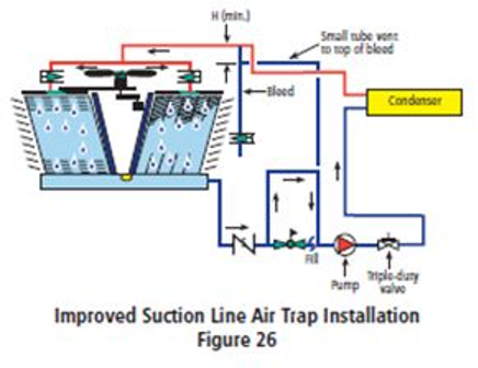
RECOMMENDATION #2: Avoid air traps caused by elevation changes in the suction pipe. Elbows used to go up & over pipe or obstacles cause an air trap. The improper use of a reducer at the pump flange can have the same effect.
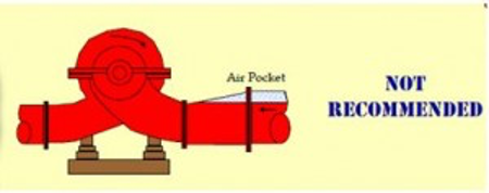
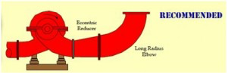
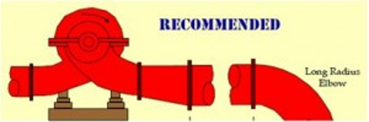
RECOMMENDATION #3: When needed, use eccentric reducers at the pump suction. The orientation depends on where the suction pipe is located.
In both examples below, we avoid trapping air while transitioning pipe sizes.
RECOMMENDATION #4: Avoid higher pressure drop items in the pump suction line. (check valves)
Engineers try to avoid raising a pipe on the tower pump suction above the tower basin. Occasionally, there is no way to avoid this and a check valve must be installed. It is critical that the check valve has a low pressure drop at design flow.
See the B&G TEH-1209 manual for more detailed instructions.
RECOMMENDATION #5: Avoid higher pressure drop items in the pump suction line. (strainers)
Strainers are a necessary evil. B&G says to avoid fine mesh strainers in the pump suction. I’ve argued that even large mesh strainers will become small mesh strainers if they have no maintenance.
I recommend you put a screen in the tower to catch the large items or you put a large mesh (.125 perf) strainer in the suction line and add a DP switch across it to indicate when the strainer needs cleaning.
With the frequent use of Bell & Gossett plate heat exchangers, the need for fine mesh straining becomes even more important. Some of the smaller plate heat exchangers require .045” perf. strainers to avoid the possibility of plugging. Condensers would also benefit from fine mesh strainers. When you must use a fine mesh strainer, locate it on discharge of the pump.
RECOMMENDATION #6 Piping Velocities:
Traditional hydronic piping system designers use tools such as the Xylem Bell & Gossett System Syzer for pipe sizing. Tower manufacturers, the Hydraulic Institute (HI), and Bell and Gossett all suggest lower velocity for pipe selection in cooling tower pump suction piping. Bell & Gossett has several pipe sizing suggestions in their manual TEH-1209A.
- The pipe velocity should not be greater than the pump suction velocity. In other words, the pipe entering the pump should not be smaller than the suction size of the pump.
- Pipe velocities should be selected for 5 to 8 feet per second (FPS) and should have a minimum of 5 pipe diameters of straight pipe before the suction side of the pump. A suction diffuser may be used in lieu of the 5 pipe diameters if the header is above and you are dropping down into the pump.
- The tower outlet pipe should be sized for 5 FPS maximum.
- Minimize the number of pipe size changes. This makes economic sense when the suction pipe is short. On two or three cell towers, keep the tower and pump piping the same as the main, if physically possible. Avoid making multiple pipe reductions in one fitting.
- Use lateral rather than bull head tees; if you have the space. This reduces turbulence entering the pump. You may detail tapered headers. (See the TEH manual)
Many an engineer will point to many a project with the comment “I’ve never had an issue using just my hydronic system standards.” The engineer is probably correct. If you do enough projects, there could be a problem job soon and these rules will help you avoid that “one time” issue.
EXAMPLE: Three towers at 2000 GPM each for a total of 6000 GPM in the pump suction header and three pumps at 2000 GPM at 50 feet each. Tower pan is 5 feet above grade.
SOLUTION: The pump is a B&G VSCS-6X8X10.5A at 40 HP with 9 feet NPSH. 2000 GPM leaving the tower should be 14” at 4.74 FPS. (Rule 3). 6000 GPM in the common pipe should be 20” at 6.92 FPS velocity. (Rule 2 and ASHRAE 90.1-2013) Pump suction pipe could be 14” or 12” and we’ll use 2 reducers to the 8” suction. This would be a great place for a 14” reducing double suction diffuser if piping permits. (Rule 1, 2, 6).
This concludes our series on Net Positive Suction Head (NPSH). Look forward to an electrical topic for mechanical engineers next week.
Check out the rest of the Net Positive Suction Head (NPSH) Series:
Part One – Terms and Definitions
Part Two – NPSH Safety factors
Part Three – Calculating NPSH Available
Part Four – Gauge Readings