Printer Friendly (PDF)
Minimum pump flow rate is critical to the trouble-free operation and longevity of the centrifugal pump. In the last blog we described the use of a Cla-Val 50-01 back pressure control valve in constant speed open pumping applications. This week we identify why that valve will not operate as expected in a closed hydronic system with or without variable speed pumps.
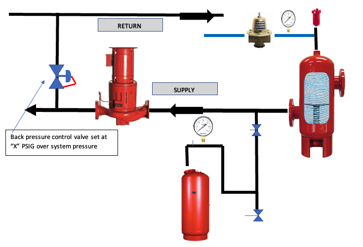
We recently reviewed a hot water heating project schematic using a back pressure valve (as shown in the above sketch). The valve senses the pressure at the inlet and opens to allow water to flow from the supply to the return if the pressure exceeds a given value. See Pump Minimum Flow Using a Cla-Val Back Pressure Valve for more information on the operation of these valves.
Closed Hydronic Heating System Pressure
We understand that the minimum cold fill pressure of the closed hydronic system is a function of elevation of the system. We also understand that the purpose of the expansion tank or compression tank is to limit the pressure increase in the system as we heat the water. That limited pressure is greater than the cold fill minimum pressure but less than the pressure that would cause the pressure relief valve to open.
The previous paragraph is a lot of words that say, “as we heat the system water, the system pressure will rise.” This has nothing to do with the pump operation. It is simply the expansion of the water based on the engineer’s design of the expansion tank.
Constant Speed Pump Discharge Pressure at Design Flow Rate
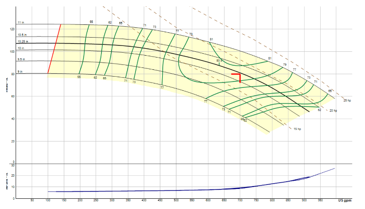
Look at the constant speed pump curve above designed for 700 GPM at 80 feet (35 PSIG). The minimum flow of this pump is shown on the red line is 125 GPM at about 105 feet (≈ 45 PSIG). If the fill or system pressure was 15 PSIG at the expansion tank, the design discharge pressure would be 15 + 35 = 50 PSIG. If the pump backs up on the curve to minimum flow, the discharge pressure would be 15 + 45 = 60 PSIG. If we set the pressure sustaining valve shown above at 58 PSIG, it would open as we back up on the curve and protect the pump.
The problem is that this occurs only at the fill pressure and temperature. What happens when we get to design temperature? The pressure will increase at the pump suction. Assume the tank was sized for 15 PSIG fill and 30 PSIG maximum. During design conditions and ignoring safety factor oversizing, the tank suction pressure would be 30 PSIG. The pump discharge pressure would be 30 + 35 = 65 PSIG. The pressure sustaining valve set at 58 PSIG would be open and would always be open. It is protecting the pump bit playing havoc with the system flow rate since it is bypassing water all the time.
Closed hydronic systems should not use a pressure sustaining or back pressure valve for pump protection.
Variable Speed Pumps and Pressure Sustaining Valves
One could argue that we don’t use these valves in heating systems but in chilled water systems, there is not much expected pressure rise during operation. Now we turn to the other concern. The vast majority of system pumps in hydronic systems are variable speed. Look at the same curve as above as a variable speed pump.
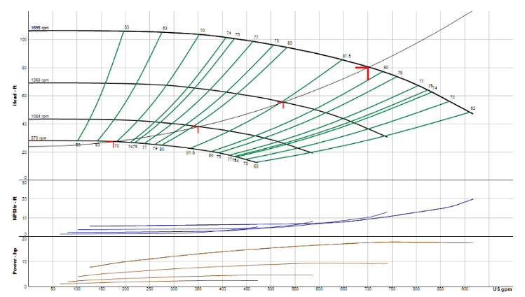
Now the speed changes as the required flow drops. The pump head also drops. The pump discharge pressure will change with temperature AND SPEED. Look at that minimum speed curve of 873 RPM. It is clear that the pump head near shutoff is around 25 feet (≈ 11 PSIG). The pump discharge pressure at minimum fill pressure is 15 + 11 = 26 PSIG. At maximum pressure, the discharge pressure will be 30 + 11 = 41 PSIG. In either case, the pressure-sustaining valve will not open.
Pressure sustaining or back pressure valves should not be used in variable speed applications.
Protecting the Hydronic System Pump in Minimum Flow Applications
What do we use to protect the pump in closed systems and variable speed systems? I’ll refer you back to my blogs.
Minimum Flow in Variable Speed Pumps for Building Hydronic HVAC Systems (Part 1)
Minimum Flow in Variable Speed Pumps for Building Hydronic HVAC Systems (Part 2)
Solving Minimum Flow in a Primary Variable System (Part 3)
Thank you for understanding how to protect your investment in Bell & Gossett pumps. Next week, we’ll look at using pump amp draw to approximate the flow rate of an installed pump.