Printer Friendly (PDF)
Part 2 of this series on expansion tank locations showed the expansion tank in a high-rise hydronic system located at the top of the system. That article described the pros and cons to attaching the tank to the return piping in the penthouse or upper floor. I received a question this week about locating the connection to the system at the traditional location in the basement and taking the tank connection all the way to the top. Today’s R. L. Deppmann Monday Morning Minutes tackles this question.
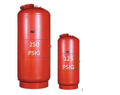
Here is the example system. It is a 30-story high rise hydronic heating system. The result was a 20% saving in first cost and a reduction in tank size if the tank was located at the top of the system. So, we know we save thousands of dollars in the first cost if the tank is on the top floor. Can the penthouse mounted tank be connected to the traditional location?
Hydronic Expansion Tank in the Penthouse with System Connection in the Traditional Location
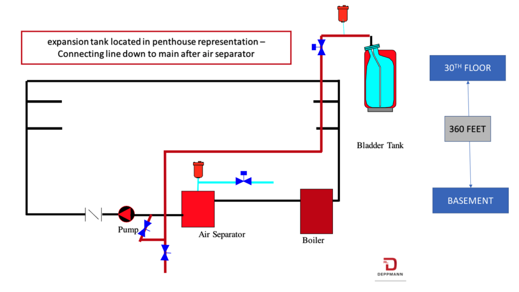
In the above system example, we show the tank mounted in the penthouse and the connection in the basement. The point of no pressure change is after the air separator and before the pump. One big advantage with this piping strategy is the location of the cold fill makeup. The cold fill pressure reducing valve (PRV) may now be set at the same pressure as in the traditional location. The PRV will be set to 160 PSIG with a 4 PSIG air charge on the expansion tank. I added an extra shutoff valve in the penthouse to allow for service of the tank and air vent.
What is the disadvantage of this “home run” pipe from the basement to the tank above?
There is one huge disadvantage that I see. It is the cost. The pipe must be run up 360 feet from the basement to the tank. It must be piped without any inverted “U” bends that might capture air. The size of the pipe will increase dramatically. Bell & Gossett has a table B on page 19 of the “Air Management” TEH-1196B technical manual. It describes the reasons for the sizing of the line between the expansion tank and the mains.
The challenge we have is the time it takes for the pressure increase to get from the heat source to the tank to regulate the pressure. As the distance from the system to the tank increases, so does the pipe size.
Table “B” shows us a pipe size of 1-1/4″ for a 100-foot run at 200°F and 5000 MBH. If the pipe length is increased to 300 feet, the pipe size will jump at least two sizes to 2”. At 400 feet we will require 2-1/2” pipe. The cost advantage of locating the tank in the penthouse starts to dissipate quickly.
By locating the tank on the main return in the penthouse, we are using the generously sized mains for this pressure transference.
The suggestion for the penthouse tank location in this example is sound. The idea of the very long pipe between the main system in the basement and the penthouse tank will significantly reduce or eliminate any cost advantage.